
Page 153 - Design of Reinforced Masonry Structures
P. 153
DESIGN OF REINFORCED MASONRY BEAMS 4.17
Thus, for the tension reinforcement strain factor a to be equal to or greater than 1.5 in a
clay masonry beam, the condition given by Eq. (4.34) should be satisfied:
c
.
≤ 0 538 (4.34)
d
Equation (4.34) states that for all values of c/d > 0.538, the value of a would be less than
1.5 in clay masonry beams having Grade 60 tension reinforcement.
Similarly, for a clay masonry beam having Grade 40 reinforcement, the c/d ratio can
be expressed as
c 0 0035
.
= = 0 628 (4.35)
.
.
d 0 0035 +1 5 0 00138)
.
(
.
Thus, for the tension reinforcement strain factor a to be equal to or greater than 1.5 in
a clay masonry beam having Grade 40 reinforcement, the condition given by Eq. (4.36)
should be satisfied:
c
≤ 0 628 (4.36)
.
d
Equations for c/d ratios corresponding to the other values of the tension reinforcement
strain factor a , for example, a = 3 and 4 (as specified in Table 4.2), can be derived fol-
lowing the above procedure.
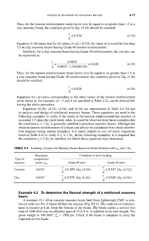
Equations (4.30), (4.32), (4.34), and (4.36) are summarized in Table 4.4 for use
in analysis and design of reinforced masonry beams. These equations are used in the
following examples to verify if the strain in the tension reinforcement has reached or
exceeded 1.5 times the yield strain value. It would be observed from these examples that
the condition e ≥ 1.5e is generally satisfied in practical masonry beams. Although the
y
s
strain in tension reinforcement of a beam can always be calculated from strain distribu-
tion diagram (using similar triangles), it is much simpler to use c/d ratios (equations
listed in Table 4.4) to verify if e ≥ 1.5e . In the following examples, it is required that
s
y
the condition e ≥ 1.5e be satisfied, for which these equations have been used.
s
y
TABLE 4.4 Limiting c/d ratios for Masonry Beams Based on Strain Gradient with e mu and 1.5e y
Maximum Condition of steel yielding
Type of compressive
masonry strain, e Grade 60 steel Grade 40 steel
mu
c c
.
.
Concrete 0.0025 d ≤ 0 454 [Eq. (4.30)] d ≤ 0 547 [Eq. (4.32)]
c c
.
.
Clay 0.0035 ≤ 0 538 [Eq. (4.34)] ≤ 0 628 [Eq. (4.36)]
d d
Example 4.2 To determine the flexural strength of a reinforced masonry
beam.
A nominal 10 × 40 in concrete masonry beam built from lightweight CMU is rein-
forced with two No. 6 Grade 60 bars for tension (Fig. E4.2). The centroid of reinforce-
ment is located at 6 in. from the bottom of the beam. The beam carries a service live
load of 1600 lb/ft over an effective span of 15 ft 8 in. in addition to its own weight. The
3
grout weight is 140 lb/ft . f ′ = 1500 psi. Check if the beam is adequate to carry the
m
imposed service loads.