
Page 151 - Design of Reinforced Masonry Structures
P. 151
DESIGN OF REINFORCED MASONRY BEAMS 4.15
TABLE 4.3 Limiting Levels of Yield Strain in Steel Reinforcement (MSJC-08 Section 3.3.3.5)
Tension reinforcement
Design element(s) strain factor, a [Eq. (4.17)] MSJC-05 Section
Masonry members where 1.5 3.3.3.5.1
M u / V u d v ≥ 1
Intermediate reinforced masonry 3 3.3.3.5.2
shear walls subject to in-plane
loads where M / V u d v ≥ 1
u
Special reinforced masonry 4 3.3.3.5.3
shear walls subject to in-plane
loads where M u / V u d v ≥ 1
Masonry members where No limit 3.3.3.5.4
M / V u d v ≤ 1 and when designed
u
using R ≤ 1.5
when designed using R ≥ 1.5 1.5
Note that MSJC-08 Section 3.3.3.5.4 provides no upper limit for maximum reinforce-
ment where the ratio M /V d ≤ 1.0 and R ≤ 1.5. This provision should not be construed to
u u v
mean that a beam can be designed as an overreinforced beam. Section 3.3.3.5.4 actually is
not applicable to transversely loaded beams discussed in this chapter. It is intended to apply
to squat shear walls (which act as vertical beams and have large d , equal to the length of
v
the shear wall, so that M /V d ≤ 1.0) in regions of low seismicity (R ≤ 1.5), where the shear
u u v
failure rather than flexural failure (because moments are small) would be dominant.
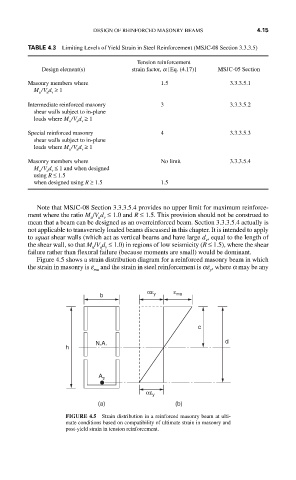
Figure 4.5 shows a strain distribution diagram for a reinforced masonry beam in which
the strain in masonry is e and the strain in steel reinforcement is ae , where a may be any
mu y
b αε y ε mu
c
h N.A. d
A s
αε y
(a) (b)
FIGURE 4.5 Strain distribution in a reinforced masonry beam at ulti-
mate conditions based on compatibility of ultimate strain in masonry and
post-yield strain in tension reinforcement.