
Page 147 - Design of Reinforced Masonry Structures
P. 147
DESIGN OF REINFORCED MASONRY BEAMS 4.11
where the depth of compression block (a) is calculated from Eq. (4.9):
Af
a = sy (4.9 repeated)
080 fb ′
.
m
Practical design of reinforced masonry beams is based on the premise that the tension
reinforcement has attained certain level of yield strain (e ≥ e ) before the onset of crush-
s y
ing of masonry when the beam is subjected to ultimate loads. Therefore, when analyzing
or designing a beam, it is required to check that reinforcement has yielded (i.e., e ≥ e ).
s y
Example 4.1 illustrates the procedure for calculating the values of parameters a, c, and the
strain in the tension reinforcement, e . Note that the strain in the tension reinforcement
s
of the beam calculated in this example is based on the ultimate strain value for concrete
masonry, e = 0.0025. If the beam were a clay masonry beam, we would use a strain value
mu
of e = 0.0035 (instead of 0.0025) to calculate strain in tension reinforcement.
mu
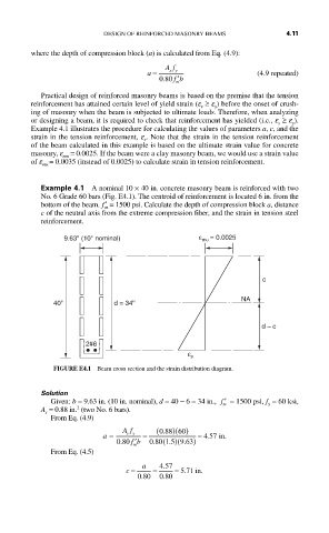
Example 4.1 A nominal 10 × 40 in. concrete masonry beam is reinforced with two
No. 6 Grade 60 bars (Fig. E4.1). The centroid of reinforcement is located 6 in. from the
bottom of the beam. f ′ = 1500 psi. Calculate the depth of compression block a, distance
m
c of the neutral axis from the extreme compression fiber, and the strain in tension steel
reinforcement.
9.63'' (10'' nominal) ε mu = 0.0025
c
NA
40'' d = 34''
d – c
2#6
ε s
FIGURE E4.1 Beam cross section and the strain distribution diagram.
Solution
Given: b = 9.63 in. (10 in. nominal), d = 40 − 6 = 34 in., ′ f = 1500 psi, f = 60 ksi,
m y
2
A = 0.88 in. (two No. 6 bars).
s
From Eq. (4.9)
Af (088 60. )( )
a = sy = = 4.557 in.
080 fb ′ m 080 (15. )(963. )
.
.
From Eq. (4.5)
.
c = a = 457 = 571 .
.
in
.
080 080
.