
Page 142 - Design of Reinforced Masonry Structures
P. 142
4.6 CHAPTER FOUR
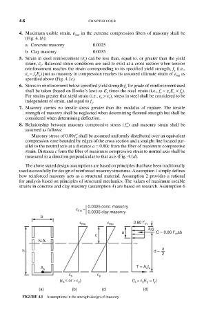
4. Maximum usable strain, e , in the extreme compression fibers of masonry shall be
mu
(Fig. 4.1b):
a. Concrete masonry 0.0025
b. Clay masonry 0.0035
5. Strain in steel reinforcement (e ) can be less than, equal to, or greater than the yield
s
strain, e . Balanced strain conditions are said to exist at a cross section when tension
y
reinforcement reaches the strain corresponding to its specified yield strength, f (i.e.,
y
e = f E ) just as masonry in compression reaches its assumed ultimate strain of e as
mu
y s
y
specified above (Fig. 4.1c).
6. Stress in reinforcement below specified yield strength f for grade of reinforcement used
y
shall be taken (based on Hooke’s law) as E times the steel strain (i.e., f = e E < f ).
s s
s
s
y
For strains greater that yield strain (i.e., e > e ), stress in steel shall be considered to be
y
s
independent of strain, and equal to f . y
7. Masonry carries no tensile stress greater than the modulus of rupture. The tensile
strength of masonry shall be neglected when determining flexural strength but shall be
considered when determining deflection.
8. Relationship between masonry compressive stress ( ′ f ) and masonry strain shall be
m
assumed as follows:
Masonry stress of 0.80 ′ f shall be assumed uniformly distributed over an equivalent
m
compression zone bounded by edges of the cross section and a straight line located par-
allel to the neutral axis at a distance a = 0.80c from the fiber of maximum compressive
strain. Distance c form the fiber of maximum compressive strain to neutral axis shall be
measured in a direction perpendicular to that axis (Fig. 4.1d).
The above stated design assumptions are based on principles that have been traditionally
used successfully for design of reinforced masonry structures. Assumption 1 simply defines
how reinforced masonry acts as a structural material. Assumption 2 provides a rational
for analysis based on principles of structural mechanics. The values of maximum useable
strains in concrete and clay masonry (assumption 4) are based on research. Assumption 6
0.0025 conc. masonry
ε mu =
0.0035 clay masonry
b
ε mu ε mu 0.80 f′ m
a /2
a C = 0.80 f′ m ab
c
N.A.
a
h d –
2
T = A s f s
A s
ε s ε y
(ε s ≤ or > ε y ) (f s = ε y E y = f y )
(a) (b) (c) (d)
FIGURE 4.1 Assumptions in the strength design of masonry.