
Page 140 - Design of Reinforced Masonry Structures
P. 140
4.4 CHAPTER FOUR
4.3.2.1 Strength Reduction Factors (e -Factors) The behavior of masonry, like that of
reinforced concrete, is different under different loading conditions. For example, its behav-
ior is different in bending than in shear, and it can be predicted with greater certainty in
bending than in shear. Members under axial loads behave differently than in flexure. Plain
masonry behaves differently than reinforced masonry. Thus, the values of f-factors are dif-
ferent for members under different loading conditions.
There are several reasons for providing strength reduction factors:
1. To allow for the probability of understrength due to variations in material strengths and
dimensions. The determination of the “nominal strength” is based on the assumption
that the member would have exact dimensions and material properties used in the cal-
culations. This assumption may not be close to reality.
2. To allow for the inaccuracies in the design equations.
3. To reflect the degree of ductility and required reliability of the member under the load
effects being considered.
4. To reflect the importance of the member in the structure.
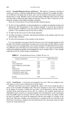
It is very important to recognize that the f-factors to be used in design depend on both
the type of the member, and the type of loading. Even for the same member, different values
of f may need to be used depending on the member strength to be determined. For example,
two different values of f-factors are used in design of beams—one value for determination
of flexural strength and another for determination of shear strength. Table 4.1 lists strength
reduction factors for various design considerations.
TABLE 4.1 Strength Reduction Factors, f [MSJC-08; Ref. 4.3]
Design consideration f MSJC-08 Section
Flexure 0.90 3.1.4.1
Axial compression 0.90 3.1.4.1
Axial compression and bending 0.90 3.1.4.1
Shear 0.80 3.1.4.3
Anchor bolts 3.1.4.4
Controlled by masonry breakout 0.50
Controlled by anchor steel 0.90
Controlled by anchor pullout 0.65
Bearing 0.60 3.1.4.5
4.3.2.2 Load Factors Load factors are assigned in two ways. They are assigned to spe-
cific loads as well as to the combination of specific loads.
Different load factors are used to augment the values of the service loads in order to
arrive at the maximum anticipated loads. The factor assigned to each load is influenced
by the degree of certainty to which the load effect can be determined, and the expected
variation in the load during the service life of a structure. For example, dead loads are
determined based on known or assumed member sizes and therefore can be determined
with reasonable degree of certainty. The live loads, on the other hand, are highly variable
by their very nature, and cannot be determined with the same degree of certainty as the
dead loads. Therefore, a higher value of load factor is assigned to the live load than to the
dead load. Uncertainty in analysis and structural behavior of a structural system are other
reasons for using load factors.