
Page 144 - Design of Reinforced Masonry Structures
P. 144
4.8 CHAPTER FOUR
b
ε mu 0.80 f′ m 0.80 f′ m
a /2
c c
a
c
h NA a
d –
2
A s
T = A s f s T = A s f s
ε y
(a) (b) (c) (d)
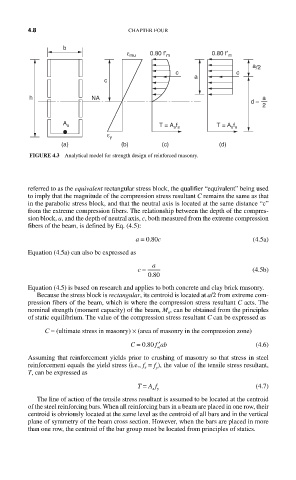
FIGURE 4.3 Analytical model for strength design of reinforced masonry.
referred to as the equivalent rectangular stress block, the qualifier “equivalent” being used
to imply that the magnitude of the compression stress resultant C remains the same as that
in the parabolic stress block, and that the neutral axis is located at the same distance “c”
from the extreme compression fibers. The relationship between the depth of the compres-
sion block, a, and the depth of neutral axis, c, both measured from the extreme compression
fibers of the beam, is defined by Eq. (4.5):
a = 0.80c (4.5a)
Equation (4.5a) can also be expressed as
c = a (4.5b)
.
080
Equation (4.5) is based on research and applies to both concrete and clay brick masonry.
Because the stress block is rectangular, its centroid is located at a/2 from extreme com-
pression fibers of the beam, which is where the compression stress resultant C acts. The
nominal strength (moment capacity) of the beam, M , can be obtained from the principles
n
of static equilibrium. The value of the compression stress resultant C can be expressed as
C = (ultimate stress in masonry) × (area of masonry in the compression zone)
′
C = 080. f ab (4.6)
m
Assuming that reinforcement yields prior to crushing of masonry so that stress in steel
reinforcement equals the yield stress (i.e., f = f ), the value of the tensile stress resultant,
s
y
T, can be expressed as
T = A f (4.7)
s y
The line of action of the tensile stress resultant is assumed to be located at the centroid
of the steel reinforcing bars. When all reinforcing bars in a beam are placed in one row, their
centroid is obviously located at the same level as the centroid of all bars and in the vertical
plane of symmetry of the beam cross section. However, when the bars are placed in more
than one row, the centroid of the bar group must be located from principles of statics.