
Page 146 - Design of Reinforced Masonry Structures
P. 146
4.10 CHAPTER FOUR
b
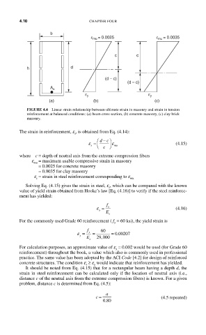
ε mu = 0.0025 ε mu = 0.0035
c c
h d
(d – c)
(d – c)
A s
ε y ε y
(a) (b) (c)
FIGURE 4.4 Linear strain relationship between ultimate strain in masonry and strain in tension
reinforcement at balanced conditions: (a) beam cross section, (b) concrete masonry, (c) clay brick
masonry.
The strain in reinforcement, e , is obtained from Eq. (4.14):
s
−
⎛ dc⎞
ε = ⎜ ⎟ ε (4.15)
s ⎝ c ⎠ mu
where c = depth of neutral axis from the extreme compression fibers
e = maximum usable compressive strain in masonry
mu
= 0.0025 for concrete masonry
= 0.0035 for clay masonry
e = strain in steel reinforcement corresponding to e
s mu
Solving Eq. (4.15) gives the strain in steel, e , which can be compared with the known
s
value of yield strain obtained from Hooke’s law [Eq. (4.16)] to verify if the steel reinforce-
ment has yielded:
f
ε = y (4.16)
y
E
s
For the commonly used Grade 60 reinforcement ( f = 60 ksi), the yield strain is
y
f 60
ε = y = = 0 00207.
y E 29 000
,
s
For calculation purposes, an approximate value of e = 0.002 would be used (for Grade 60
y
reinforcement) throughout the book, a value which also is commonly used in professional
practice. The same value has been adopted by the ACI Code [4.2] for design of reinforced
concrete structures. The condition e ≥ e would indicate that reinforcement has yielded.
s y
It should be noted from Eq. (4.15) that for a rectangular beam having a depth d, the
strain in steel reinforcement can be calculated only if the location of neutral axis (i.e.,
distance c of the neutral axis from the extreme compression fibers) is known. For a given
problem, distance c is determined from Eq. (4.5):
c = a (4.5 repeated)
080
.