
Page 143 - Design of Reinforced Masonry Structures
P. 143
DESIGN OF REINFORCED MASONRY BEAMS 4.7
is a stipulation of Hooke’s law. Tensile strength of masonry is very small and ineffective
in resisting flexural loads; accordingly, it is ignored in calculation of flexural strength.
However, it contributes to the overall stiffness of a masonry element and, therefore, is to be
considered for deflection calculations (assumption 7).
The definition of distribution of compressive stress in a masonry element in flexure
(assumption 8) is parallel to that used for design of a similar reinforced concrete element.
For a reinforced concrete element in flexure, distance a is defined in ACI 318 [4.2] as a =
b c, where b is a coefficient whose value depends on the compressive strength of concrete
1
1
and varies between 0.85 and 0.65. For the commonly used range of masonry strengths (1500
psi < f ′ < 6000 psi) that have been investigated, the value of b is taken as a constant value of
1
m
0.80 for design of masonry structures (symbol b is not used in the MSJC Code).
1
The analytical model based on the forgoing assumptions is illustrated in Fig. 4.1.
4.5 ANALYSIS OF RECTANGULAR SECTIONS
IN FLEXURE
4.5.1 Principles of Flexural Analysis in Strength Design
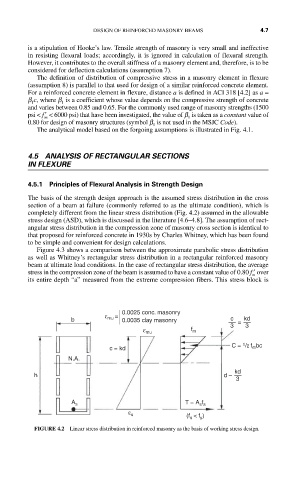
The basis of the strength design approach is the assumed stress distribution in the cross
section of a beam at failure (commonly referred to as the ultimate condition), which is
completely different from the linear stress distribution (Fig. 4.2) assumed in the allowable
stress design (ASD), which is discussed in the literature [4.6–4.8]. The assumption of rect-
angular stress distribution in the compression zone of masonry cross section is identical to
that proposed for reinforced concrete in 1930s by Charles Whitney, which has been found
to be simple and convenient for design calculations.
Figure 4.3 shows a comparison between the approximate parabolic stress distribution
as well as Whitney’s rectangular stress distribution in a rectangular reinforced masonry
beam at ultimate load conditions. In the case of rectangular stress distribution, the average
stress in the compression zone of the beam is assumed to have a constant value of 080. ′ f over
m
its entire depth “a” measured from the extreme compression fibers. This stress block is
0.0025 conc. masonry
ε mu =
b 0.0035 clay masonry c = kd
3 3
f m
ε mu
c = kd C = 1 /2 f m bc
N.A.
kd
h d –
3
A s T = A s f s
ε s (f s < f y )
FIGURE 4.2 Linear stress distribution in reinforced masonry as the basis of working stress design.