
Page 150 - Design of Reinforced Masonry Structures
P. 150
4.14 CHAPTER FOUR
and 40 reinforcing bars. For all cases when c < d/2, the strain in tension reinforcement (e )
s
would be greater than the ultimate strain in masonry, e . This is an important observation
mu
for it provides a quick check (without any additional calculations) whether the reinforce-
ment has yielded.
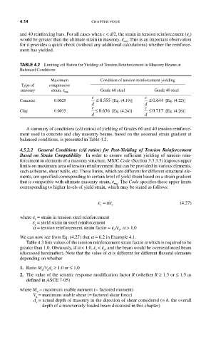
TABLE 4.2 Limiting c/d Ratios for Yielding of Tension Reinforcement in Masonry Beams at
Balanced Conditions
Maximum Condition of tension reinforcement yielding
Type of compressive
masonry strain, e mu Grade 60 steel Grade 40 steel
c c
.
.
Concrete 0.0025 ≤ 0 555 [Eq. (4.19)] ≤ 0 644 [Eq. (4.22)]
d d
c c
.
.
Clay 0.0035 ≤ 0 636 [Eq. (4.24)] ≤ 0 717 [Eq. (4.26)]
d d
A summary of conditions (c/d ratios) of yielding of Grades 60 and 40 tension reinforce-
ment used in concrete and clay masonry beams, based on the assumed strain gradient at
balanced conditions, is presented in Table 4.2.
4.5.2.2 General Conditions (c/d ratios) for Post-Yielding of Tension Reinforcement
Based on Strain Compatibility In order to ensure sufficient yielding of tension rein-
forcement in elements of a masonry structure, MSJC Code (Section 3.3.3.5) imposes upper
limits on maximum area of tension reinforcement that can be provided in various elements,
such as beams, shear walls, etc. These limits, which are different for different structural ele-
ments, are specified corresponding to certain level of yield strain based on a strain gradient
that is compatible with ultimate masonry strain, e . The Code specifies these upper limits
mu
corresponding to higher levels of yield strain, which may be stated as follows:
ε = αε (4.27)
s y
where e = strain in tension steel reinforcement
s
e = yield strain in steel reinforcement
y
a = tension reinforcement strain factor = e /e , a > 1.0
s y
We can now see from Eq. (4.27) that a = 6.2 in Example 4.1.
Table 4.3 lists values of the tension reinforcement strain factor a which is required to be
greater than 1.0. Obviously, if a < 1.0, e < e , and the beam would be overreinforced beam
y
s
(discussed hereinafter). Note that the value of a is different for different flexural elements
depending on whether
1. Ratio M /V d ≥ 1.0 or ≤ 1.0
u u v
2. The value of the seismic response modification factor R (whether R ≥ 1.5 or ≤ 1.5 as
defined in ASCE 7-05)
where M = maximum usable moment (= factored moment)
u
V = maximum usable shear (= factored shear force)
u
d = actual depth of masonry in the direction of shear considered (= h, the overall
v
depth of a transversely loaded beam discussed in this chapter)