
Page 157 - Design of Reinforced Masonry Structures
P. 157
DESIGN OF REINFORCED MASONRY BEAMS 4.21
The next example presents a brick (or clay masonry) beam. The analysis and design
procedures for structural clay masonry are same as for concrete masonry. The only dif-
ference is that the value of ultimate strain in clay masonry (0.0035) is much higher than
ultimate strain in concrete masonry (0.0025). Therefore, strain in steel at ultimate load
conditions, e , would be determined based on e = 0.0035. Accordingly, Eqs. (4.34) (for
mu
s
Grade 60 steel) and (4.36) (for Grade 40 steel) can be used to verify if the reinforcement
has yielded. Of course, if c is less than d/2 as before, e > e >e .
s
mu
y
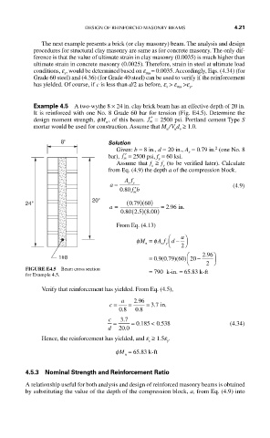
Example 4.5 A two-wythe 8 × 24 in. clay brick beam has an effective depth of 20 in.
It is reinforced with one No. 8 Grade 60 bar for tension (Fig. E4.5). Determine the
design moment strength, φM , of this beam. ′ f = 2500 psi. Portland cement Type S
n m
mortar would be used for construction. Assume that M / V d ≥ 1.0.
u
u v
8" Solution
2
Given: b = 8 in., d = 20 in., A = 0.79 in. (one No. 8
s
bar), ′ f = 2500 psi, f = 60 ksi.
m
y
Assume that f ≥ f (to be verified later). Calculate
s
y
from Eq. (4.9) the depth a of the compression block.
Af
a = sy (4.9)
.
080 fb ′ m
20"
24" a = (079 60. )( ) = 296 in
.
.
.
080 (25. )(800. )
From Eq. (4.13)
φM = φA f ⎛ d − a ⎞
n s y ⎝ ⎠ 2
⎛ 296 ⎞
.
1#8 = 09 079 60 20.( . )( ) −
⎝ 2 ⎠
FIGURE E4.5 Beam cross section
.
for Example 4.5. = = 790 k-in. = 65 83 k-ft
Verify that reinforcement has yielded. From Eq. (4.5),
.
.
.
c = a = 296 = 37 in
.
.
08 08
c 37 .
= = 0 185 < 0 538 (4.34)
.
.
d 20 0 .
Hence, the reinforcement has yielded, and e ≥ 1.5e .
y
s
φM = 65.83 k-ft
n
4.5.3 Nominal Strength and Reinforcement Ratio
A relationship useful for both analysis and design of reinforced masonry beams is obtained
by substituting the value of the depth of the compression block, a, from Eq. (4.9) into