
Page 222 - Design of Reinforced Masonry Structures
P. 222
4.86 CHAPTER FOUR
span plus 8 in., arching action is assumed to be present and the dead and the live
loads are transferred to the adjacent masonry through the arching action; no part of
this load is carried by the lintel. On the other hand, if the floor or the roof line lies
below this height, the load from the wall must be carried as a uniform load by the
lintel distributed over the entire span (Fig. 4.22b). In addition, there may be loads
distributed uniformly only on a portion of the span.
b. Concentrated load
A method for determination of dispersion/distribution of concentrated loads on
walls is recommended by NCMA [4.14] and BIA [4.15], which is based on test
results reported in the literature [4.16, 4.17].
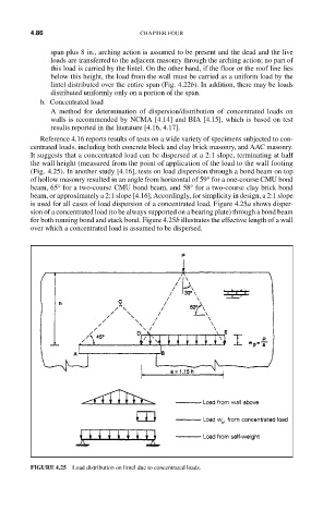
Reference 4.16 reports results of tests on a wide variety of specimens subjected to con-
centrated loads, including both concrete block and clay brick masonry, and AAC masonry.
It suggests that a concentrated load can be dispersed at a 2:1 slope, terminating at half
the wall height (measured from the point of application of the load to the wall footing
(Fig. 4.25). In another study [4.16], tests on load dispersion through a bond beam on top
of hollow masonry resulted in an angle from horizontal of 59° for a one-course CMU bond
beam, 65° for a two-course CMU bond beam, and 58° for a two-course clay brick bond
beam, or approximately a 2:1 slope [4.16]. Accordingly, for simplicity in design, a 2:1 slope
is used for all cases of load dispersion of a concentrated load. Figure 4.25a shows disper-
sion of a concentrated load (to be always supported on a bearing plate) through a bond beam
for both running bond and stack bond. Figure 4.25b illustrates the effective length of a wall
over which a concentrated load is assumed to be dispersed.
FIGURE 4.25 Load distribution on lintel due to concentrated loads.