
Page 227 - Design of Reinforced Masonry Structures
P. 227
4.90 CHAPTER FOUR
L L
D
(a)
L
D D
(b)
L
D
B
(c)
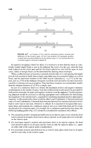
FIGURE 4.27 (a) Position of live load for maximum positive moment and
deflection in the exterior span, (b) live load position for maximum positive
moment and maximum deflection in the interior span, (c) live load position for
maximum negative moment at support B.
In regard to designing a lintel for shear, it is instructive to note that the shear in a uni-
formly loaded simple beam is zero at the midspan, but such is not the case when the dead
load is placed on the entire span and the live load is placed on only half the span. In such
cases, values of design shears can be determined by drawing shear envelopes.
When a sufficient mass of masonry is present on both sides of a wall opening that might
provide full restraint to lintel, then a single-span lintel may be assumed to behave as a fixed
2
beam, and the maximum moment in the lintel may be calculated as –w L /12 at the sup-
u
2
port, and +w L /24 at the midspan. Designers would be well advised to use their discretion
u
carefully in making such an assumption. Note that these moments are considerably smaller
2
than the midspan moment of wL /8 in a simple span.
In case of a continuous lintel (or a beam), the maximum positive and negative moments
would depend on the number of spans. Note that reinforcement would need to be provided for
both positive moments (in spans) and negative moments (over the supports). Careful engineer-
ing judgment should be exercised in selecting appropriate load combination for determining
the magnitude of the uniform load w required for calculating maximum positive and negative
u
moments. As discussed earlier, these would be either Load Combination 1 (factored dead load
only) or Load Combination 2 (factored dead load plus factored live load plus factored roof live
load or snow load or rain load, whichever is critical). It is important to recognize that maxi-
mum shears and moments in a continuous span do not occur when both dead and live loads
are placed on all contiguous spans. For example, for a continuous span having three spans, the
following loading pattern (Fig. 4.27) should be considered for maximum force effects:
1. The maximum positive moment and deflection in an interior span occurs when the dead
load is placed on all spans (dead load is always present on all spans) plus live load only
on the interior span.
2. For maximum negative moment and maximum shear at an interior support, the dead
load should be placed on all spans and live load on only the adjacent spans (i.e., spans
on either side of the support under consideration).
3. For maximum moment and deflection in an exterior span, place dead load on all spans
and live load only on the exterior spans.