
Page 228 - Design of Reinforced Masonry Structures
P. 228
DESIGN OF REINFORCED MASONRY BEAMS 4.91
For more than three continuous spans, load positions for maximum effects would be dif-
ferent. All possible loading combinations and load positions should be thoroughly analyzed
in order to properly reinforce continuous masonry beams. A comprehensive discussion on
analysis of structural loads on buildings can be found in Ref. 4.13. A discussion on design
of lintels can be found in Refs. [4.14, 4.15].
4.13.2.6 Deflection Considerations for Lintels Deflection of a lintel may become a lim-
iting design criterion in some cases from the serviceability standpoint. For example, if
the lintel supports some sort of brittle nonstructural element such as a plastered ceiling,
deflection of beam may be detrimental to that element. Similarly, appreciable deflection
of a lintel may cause malfunction while operating the doors of the openings. In such cases,
code-imposed deflection limitations should be observed.
Beam deflections constitute serviceability criteria under strength design philosophy,
and are discussed later in this chapter.
4.13.2.7 Examples on Lintels Example 4.26 presents analysis of loads on lintels based
on the above described simplified approach. The example involves two types of openings:
one that qualifies for the arching action and the other that does not. Once design forces
(shears and moments) on lintels are determined, they can be designed as beams illustrated
in previous examples.
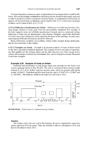
Example 4.26 Analysis of loads on lintels.
Establish load distribution on and design shears and moments for the lintels over
various openings shown in Fig. E4.26A. The wall is constructed from normal weight
nominal 8 × 8 × 16 in. hollow concrete masonry units, which are grouted solid (grout
2
2
3
weight 140 lb/ft ). Total dead and live load from the roof is 32 lb/ft (D = 12 lb/ft and
2
L = 20 lb/ft ). The tributary width for the lintel for roof loads is 10 ft.
Parapet
2'-8"
Roof line 5'-4"
20'
4' 12'
4'
12' 20' 8' 8' 5'-4" 5'-4" 4' 8' 12'
80'-0"
FIGURE E4.26A Wall elevation of a reinforced masonry building.
Solution
The subject wall is the east wall of the building. Its roof is supported by transverse
girders spaced at 20 ft on centers. Thus, the tributary width for each girder is 20 ft, and
that for the subject wall is 10 ft.