
Page 241 - Design of Reinforced Masonry Structures
P. 241
4.104 CHAPTER FOUR
2
2
F = 025 f ′ m ⎢ ⎛ ⎡ 70 r ⎞ ⎤ ⎥ = 0 25 1500) ⎢ ⎛ ⎡ 70 ⎞ ⎤ ⎥ = 107 22 lb/ft 2 < 144 lb/ft 3 NG
.
.
. (
a ⎝ h ⎠ ⎝ 130 9 . 1 ⎠
⎣ ⎦ ⎣ 1 ⎦
b. Calculate flexural stress and required reinforcement:
For single span beams, e = ½
β = h = 24 = 1
l 2 224) 2
(
⎛ w⎞
Flexural stress = (coefficient from Table 4.9) ⎜ ⎟
⎝ b ⎠
where
2500
.
.
w = load per inch of wall = = 208 3 lb/in
12
From Table 4.9, for b = ½, Coefficient = +0.75 (top of beam)
Coefficient = −1.2 (bottom of beam)
⎛ w⎞ ⎛ 208 3⎞
.
2
Flexural stress (top) = 0.75 ⎜ ⎟ = 0.75 ⎜ ⎟ = 20.5 lb/in. (compression)
⎝ b ⎠ ⎝ 7 625⎠
.
Allowable compressive stress = 0.33 ′ f = 0.33(1500)
m
2
2
= 495 lb/in. > 20 lb/in. OK
⎛ w⎞ ⎛ 208 3⎞
.
2
Flexural stress (bottom) = −1.2 ⎜ ⎟ = −1.2 ⎜ ⎟ = −32.8 lb/in. (tension)
⎝ b ⎠ ⎝ 7 625⎠
.
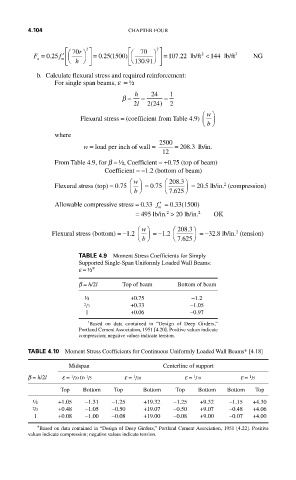
TABLE 4.9 Moment Stress Coefficients for Simply
Supported Single-Span Uniformly Loaded Wall Beams:
e = ½ ∗
b = h/2l Top of beam Bottom of beam
½ +0.75 −1.2
2 3 +0.33 −1.05
/
1 +0.06 −0.97
*
Based on data contained in “Design of Deep Girders,”
Portland Cement Association, 1951 [4.20]. Positive values indicate
compression; negative values indicate tension.
TABLE 4.10 Moment Stress Coefficients for Continuous Uniformly Loaded Wall Beams∗ [4.18]
Midspan Centerline of support
b = h/2l e = 1 20 to 1 5 e = 1 20 e = 1 10 e = 1 5
/
/
/
/
/
Top Bottom Top Bottom Top Bottom Bottom Top
½ +1.05 −1.31 −1.25 +19.32 −1.25 +9.32 −1.15 +4.30
2 /3 +0.48 −1.05 −0.50 +19.07 −0.50 +9.07 −0.48 +4.06
1 +0.08 −1.00 −0.08 +19.00 −0.08 +9.00 −0.07 +4.00
∗ Based on data contained in “Design of Deep Girders,” Portland Cement Association, 1951 [4.22]. Positive
values indicate compression; negative values indicate tension.