
Page 243 - Design of Reinforced Masonry Structures
P. 243
4.106 CHAPTER FOUR
c. Calculate the shear stress and the required shear reinforcement. Assume that
critical section is located at 0.15 l from the face of support, where l clear span
n
n
between supports.
0.15l = 0.15 (24 − 2) = 3.3 ft
n
At the critical section, the maximum shear is
⎡ L ⎤ ⎡ 24 ⎤
V = w − (. + ) 2500) − (. + 199 250, lb
33 1 =)
3 3 1 = (
⎢ ⎣ 2 ⎥ ⎦ ⎢ ⎣ 2 ⎥ ⎦
The shear stress at the critical section is
,
2
.
v = V = 19 250 = 89 lb/in.
bd (. ) (
7 625 284)
2
.
.
(
Allowable shear stress = 1 1. f m ′ = 1 1 1500) = 42 6 lb/in.
(without shear reinforcement)
Therefore, no special shear reinforcement is required.
2
Minimum wall reinforcement = 0.002 (7.625)(12) = 0.183 in. /ft *
*
( Total in both direction; no more than / 3 in one direction)
2
Provide No. 5 bars at 32 in. o.c. in horizontal direction, A = 0.115 in. 2
s
Provide No. 5 bars at 48 in. o.c. in vertical direction, A = 0.077 in. 2
s
Total reinforcement,
2
2
A = 0.115 + 0.077 = 0.192 in. > 0.183 in. OK
s
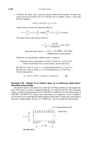
Example 4.29 Design of an interior span of a continuous deep beam:
allowable stress design.
The interior span of a nominal 12 in. wide and 15 ft high continuous wall panel mea-
sures 30 ft center-to-center of supports which are 3 ft wide (Fig. E4.29). The wall panel
carries a uniform superimposed load of 3500 lb/ft in addition to its own dead weight of
2
1500 lb/ft (100 lb/ft of its surface area). Determine (a) compressive stress at supports,
(b) flexural stresses and required tensile reinforcement, and (c) shear stress and required
2
transverse reinforcement. Assume ′ f = 2000 lb/in. , and use Grade 60 reinforcement.
m
W = superimposed load
+
Dead load
h = 15'
3' 3'
L = 30'
FIGURE E4.29