Page 240 - Design of Reinforced Masonry Structures
P. 240

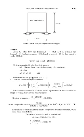
DESIGN OF REINFORCED MASONRY BEAMS         4.103


                             Wall thickness = 8"
                                                      h = 24'


                                2'     2'

                                  L = 24'

                       FIGURE E4.28  Wall panel supported over bearing pads.


           Solution
                              2
             Given:  ′ f  = 1500 lb/ft , wall thickness, b = t = 7.625 in. (8 in. nominal), wall
                    m
           height, h = 24 ft, effective span L = 24 ft, length of support = 2.0 ft., dead weight of
           wall = 100 lb/ft 2
                             Gravity load on wall = 2500 lb/ft
             Maximum permitted bearing length of supports
                    = 0.1 (distance between vertical supporting edge members)
                    = 0.1(24)
                    = 2.4 ft > 2.0 ft       OK

             Allowable stress design approach (Ref. 4.18):
           a.  Calculate allowable compressive stress:
                            ⎡  ⎛  h ⎞ ⎤        ⎡  ⎛  ( 24))( )12  ⎞  3 ⎤
                                   3
                           m ⎢
                                                                      2
                   F = 020  f ′ 1 −  ⎥  = 0 20 1500 1 ⎢  −  ⎜  ⎟ ⎥ =  154 lb/ft
                                              )
                                        .
                                          (
                        .
                    a             t ⎠             ⎝        )⎠
                            ⎣  ⎝ 48  ⎦         ⎣ ⎢  (48 )( .625  ⎦ ⎥
                                                       7
             Actual compressive stress is calculated on area equal to the wall thickness times the
           length of bearing plus twice the panel thickness.
                                      (
                              wL  2500 24)
             Reaction at supports =   =   =  30 000 lb
                               2     2
                                             ,
                                     ,
         Actual compressive stress =  30 000  = 144 lb/ft 2  < F  = 154 lb/ft 2  OK
                                                              4
                              (.   [12 + 2 7 625) ]       a
                              7 625)
                                        (.
            Commentary: If we calculate the allowable compressive stress based on MSJC-08, its
            value would be as follows:
                         The radius of gyration for an 8 in. nominal wall,
                               r = 0.289t = 0.289 (7.625) = 2.2 in.
                                    12
                              h  (24 )( )
                               =       = 130 .91  > 99
                              r    . 22
   235   236   237   238   239   240   241   242   243   244   245