
Page 247 - Design of Reinforced Masonry Structures
P. 247
4.110 CHAPTER FOUR
Anchor bolt 8"
Pea concrete
Bars in block
16" 2 Rebar typical at
Bond beam bars lintels, 1 rebar
typical for horizontal
Bond beam bond beams in wall
bars
Wire mesh
Pea
concrete
Bond beam
masonry unit
Regular
stretchers Special paper allows
partial grouting
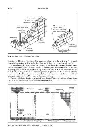
FIGURE 4.30 Section of a typical bond beam.
case, the bond beam can be designed to carry gravity loads from the roof or the floor, which
cannot be transferred to these walls since they are designed as nonload-bearing walls.
In retaining walls, bond beams can be used as an alternative to providing horizontal
reinforcement to distribute stresses that occur due to expansion and contraction of the wall.
Typically, bond beam is provided at the top of the wall, and at 16 in. on center below. For
8-in. thick retaining walls, it is a common practice to provide two No. 4 bars in all bond
beam courses. For 12-in. thick retaining walls, two No.5 bars are provided in the bond beam
course at the top, and two No. 4 bars in the courses below.
Figure 4.30 shows details of a typical bond beam. Figure 4.31 shows a bond beam
located at the roof level of a reinforced masonry building.
Parapet
Roof Bond beam
Column pilaster
Floor tie Floor
FIGURE 4.31 Bond beam located at roof level. (Courtesy: NCMA.)