
Page 252 - Design of Reinforced Masonry Structures
P. 252
DESIGN OF REINFORCED MASONRY BEAMS 4.115
The bond beam is thus subjected to an axial force of 24 kips, which must be resisted
by the reinforcement only. Calculate the tensile steel required from Eq. (4.134):
T 24
2
.
s A = = = 044 in.
φ f 09 60)
.(
y
Provide two No. 5 Grade 60 bars,
2
A = 0.61 in. OK (Table A.9)
s
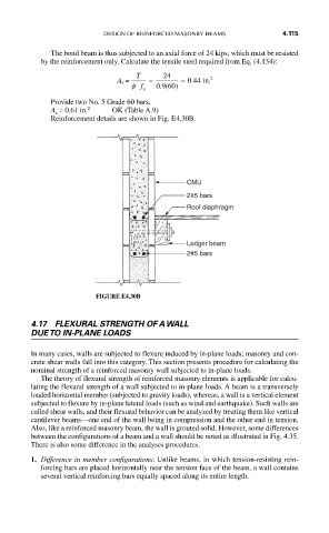
Reinforcement details are shown in Fig. E4.30B.
CMU
2#5 bars
Roof diaphragm
Ledger beam
2#5 bars
FIGURE E4.30B
4.17 FLEXURAL STRENGTH OF A WALL
DUE TO IN-PLANE LOADS
In many cases, walls are subjected to flexure induced by in-plane loads; masonry and con-
crete shear walls fall into this category. This section presents procedure for calculating the
nominal strength of a reinforced masonry wall subjected to in-plane loads.
The theory of flexural strength of reinforced masonry elements is applicable for calcu-
lating the flexural strength of a wall subjected to in-plane loads. A beam is a transversely
loaded horizontal member (subjected to gravity loads), whereas, a wall is a vertical element
subjected to flexure by in-plane lateral loads (such as wind and earthquake). Such walls are
called shear walls, and their flexural behavior can be analyzed by treating them like vertical
cantilever beams—one end of the wall being in compression and the other end in tension.
Also, like a reinforced masonry beam, the wall is grouted solid. However, some differences
between the configurations of a beam and a wall should be noted as illustrated in Fig. 4.35.
There is also some difference in the analyses procedures.
1. Difference in member configurations: Unlike beams, in which tension-resisting rein-
forcing bars are placed horizontally near the tension face of the beam, a wall contains
several vertical reinforcing bars equally spaced along its entire length.