
Page 249 - Design of Reinforced Masonry Structures
P. 249
4.112 CHAPTER FOUR
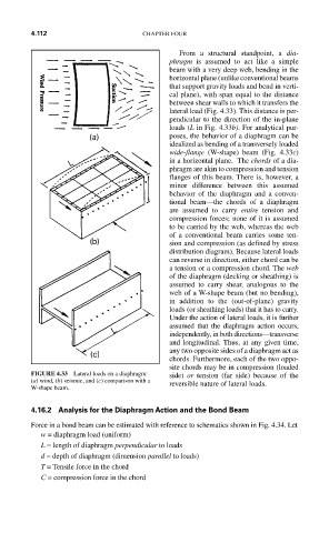
From a structural standpoint, a dia-
phragm is assumed to act like a simple
beam with a very deep web, bending in the
horizontal plane (unlike conventional beams
that support gravity loads and bend in verti-
cal plane), with span equal to the distance
between shear walls to which it transfers the
lateral load (Fig. 4.33). This distance is per-
pendicular to the direction of the in-plane
loads (L in Fig. 4.33b). For analytical pur-
poses, the behavior of a diaphragm can be
idealized as bending of a transversely loaded
wide-flange (W-shape) beam (Fig. 4.33c)
in a horizontal plane. The chords of a dia-
phragm are akin to compression and tension
flanges of this beam. There is, however, a
minor difference between this assumed
behavior of the diaphragm and a conven-
tional beam—the chords of a diaphragm
are assumed to carry entire tension and
compression forces; none of it is assumed
to be carried by the web, whereas the web
of a conventional beam carries some ten-
sion and compression (as defined by stress
distribution diagram). Because lateral loads
can reverse in direction, either chord can be
a tension or a compression chord. The web
of the diaphragm (decking or sheathing) is
assumed to carry shear, analogous to the
web of a W-shape beam (but no bending),
in addition to the (out-of-plane) gravity
loads (or sheathing loads) that it has to carry.
Under the action of lateral loads, it is further
assumed that the diaphragm action occurs,
independently, in both directions—transverse
and longitudinal. Thus, at any given time,
any two opposite sides of a diaphragm act as
chords. Furthermore, each of the two oppo-
site chords may be in compression (loaded
FIGURE 4.33 Lateral loads on a diaphragm: side) or tension (far side) because of the
(a) wind, (b) seismic, and (c) comparison with a reversible nature of lateral loads.
W-shape beam.
4.16.2 Analysis for the Diaphragm Action and the Bond Beam
Force in a bond beam can be estimated with reference to schematics shown in Fig. 4.34. Let
w = diaphragm load (uniform)
L = length of diaphragm perpendicular to loads
d = depth of diaphragm (dimension parallel to loads)
T = Tensile force in the chord
C = compression force in the chord