
Page 254 - Design of Reinforced Masonry Structures
P. 254
DESIGN OF REINFORCED MASONRY BEAMS 4.117
bars cannot be assumed to have yielded. Therefore, several trials may be necessary to
determine the position of neutral axis in a wall. The procedure begins by selecting an
arbitrary (but reasonable) value of the distance of neutral axis from the compression face
of the wall (c). Also, in the wall analysis, the compression forces in bar(s) located in
the compression zone of the wall (i.e., bars located near the compression face of wall) is
taken into account when considering equilibrium (no such consideration for analysis of
typical reinforced masonry beams). Once the position of neutral axis is located, stresses
(and hence the forces) in reinforcing bars, which may be in compression or tension, are
determined based on strain in them, which, in turn, are calculated from Hooke’s law
(maximum bar stress limited to 60 ksi for Grade 60 bars, which corresponds to a yield
strain of 0.00207). The analysis procedure for deter mining the flexural strength walls
subjected to in-plane loads is presented in Chap. 7.
4.18 DEVELOPMENT LENGTHS
FOR REINFORCING BARS
Reinforced masonry members are designed on the basic premise that grout surrounding
reinforcing bars would transfer forces from reinforcing bars to the masonry. (The same
is true for reinforced concrete members which are designed on the premise that the sur-
rounding concrete would transfer forces from reinforcing bars to the concrete.) The length
of the reinforcing bars over which forces (or stresses) are transferred from the grout to the
masonry is called the development length.
The requirements for development lengths of reinforcing bars are the same for both allow-
able stress design (ASD) and strength design, and are covered in MSJC-08 Section 3.3.3.
All reinforcing bars (in compression or tension) must extend from the point of maximum
moment in either direction a distance equal to the development length as determined from
Eq. (4.135), but not less than 12 in.:
2
.
013 df γ
l = b y (4.135)
Kf ′ m
d
where l = development length of bar
d
d = diameter of bar
b
f = yield stress of reinforcement, lb/in. 2
y
K = the least of (1) masonry cover, (2) spacing between the adjacent reinforcement,
(3) 5 times d b
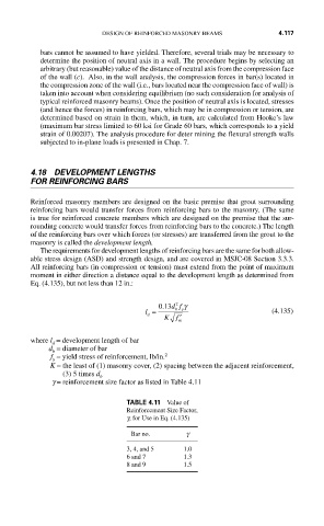
g = reinforcement size factor as listed in Table 4.11
TABLE 4.11 Value of
Reinforcement Size Factor,
g, for Use in Eq. (4.135)
Bar no. g
3, 4, and 5 1.0
6 and 7 1.3
8 and 9 1.5