
Page 256 - Design of Reinforced Masonry Structures
P. 256
DESIGN OF REINFORCED MASONRY BEAMS 4.119
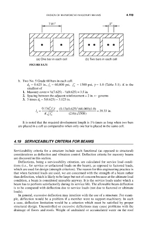
7.81'' 2''
(a) One bar in each cell (b) Two bars in each cell
FIGURE E4.31
b. Two No. 5 Grade 60 bars in each cell.
d = 0.625 in., f = 60,000 psi, ′ f = 1500 psi, g = 1.0 (Table 5.1). K is the
y
b
m
smallest of
1. Masonry cover = ½(7.625) – ½(0.625) = 3.5 in.
2. Spacing between the adjacent reinforcement = 2 in. ← governs
3. 5 times d = 5(0.625) = 3.125 in.
b
2
2
013 df γ ( 0 13 0 625) ( 60 000 1.0)
.
.
)(
.
)(
,
0
l = b y = = 39 33 in.
.
Kf ′ m (.)( 1500)
d
2 0
It is noted that the required development length is 1½ times as long when two bars
are placed in a cell as compared to when only one bar is placed in the same cell.
4.19 SERVICEABILITY CRITERIA FOR BEAMS
Serviceability criteria for a structure include such functional (as opposed to structural)
considerations as deflection and vibration control. Deflection criteria for masonry beams
are discussed in this section.
Deflections, being a serviceability criterion, are calculated for service load condi-
tions (i.e., for service or unfactored loads on the beam), as opposed to factored loads,
which are used for design (strength criterion). The reason for this engineering practice is
that when factored loads are used, we are concerned with the strength of a beam rather
than deflection, which is likely to be large but not of concern because at the ultimate load
condition, a beam is considered unusable anyway. It is the service loads under which a
beam has to perform satisfactorily during its service life. The allowable beam deflection
is to be compared with deflection due to service loads (not due to factored or ultimate
loads).
In general, excessive deflection may interfere with the use of a structure. For exam-
ple, deflection would be a problem if a member were to support machinery. In such
a case, deflection limitation would be a criterion which must be satisfied by proper
structural design. Uncontrolled or excessive deflections may cause problems with the
drainage of floors and roofs. Weight of undrained or accumulated water on the roof