
Page 259 - Design of Reinforced Masonry Structures
P. 259
4.122 CHAPTER FOUR
equivalent area of the masonry, with its centroid located at the centroid of tension rein-
forcement so that the resultant tensile force is assumed to act at this level. This principle is
equally applicable to composite sections that consist of brick and concrete masonry units,
in which case the area of one type of masonry unit (e.g., brick) can be transformed into
an equivalent area of the masonry unit of the other type (e.g., concrete block). The gen-
eral principle of transformed section is applied in the following derivations for reinforced
masonry sections.
4.20.2 Location of Neutral Axis in a Reinforced Masonry
Beam under Service Loads
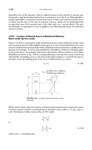
Figure 4.36 shows a rectangular singly reinforced masonry section in flexure having a total
cross-sectional area of tensile reinforcement equal to A . It is assumed that there is no com-
s
pression reinforcement present in the beam. Although reinforced masonry is neither homo-
geneous nor isotropic, it will be assumed that the assumptions of theory of bending apply
as discussed above. Accordingly, both strains and stresses will be assumed to have linear
distribution as shown in Fig. 4.36. It is assumed that there is no slip between the reinforcing
steel and the surrounding grout so the strain in the reinforcement (e ) would be the same as
s
the strain in the surrounding grout at the level of reinforcement (e ), that is,
m
e = e (4.138)
m s
0.0025 conc. masonry
e mu =
b 0.0035 clay masonry
e m
c = kd
N.A.
h
A s
e s
FIGURE 4.36 A singly reinforced masonry section
in flexure.
Within elastic limits, strains in masonry and steel reinforcement can be expressed in terms
of stresses and the modulus of elasticity based on Hooke’s law, so that e = f /E . and e =
s
m
m
m
f /E . Substitution of these values in Eq. (4.138) yields
s
s
f f
m = s
E m E s
or
f E
s = s = n (4.139)
f m E m
where E /E = n (modular ratio)
m
s