
Page 262 - Design of Reinforced Masonry Structures
P. 262
DESIGN OF REINFORCED MASONRY BEAMS 4.125
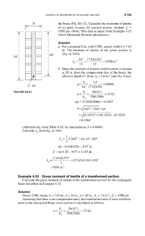
9" the beam (Fig. E4.32). Calculate the moments of inertia
of (a) gross section, (b) cracked section. Assume ′ f =
m
1500 psi. (Note: This data is taken from Example 4.12
which illustrated flexural calculations.)
Solution
a. For a nominal 8-in. wide CMU, actual width b = 7.63
in. The moment of inertia of the gross section is
20" [Eq. (4.145)]
24" 3 3
763 24)
I = bh = (. ) ( = 8790in. 4
g
12 12
b. Since the centroid of tension reinforcement is located
at 20 in. from the compression face of the beam, the
2
effective depth d = 20 in. A = 1.0 in. (one No. 9 bar).
s
.
ρ= A s = 10 =0 0066.
#4 bd (. ) (
763 20)
6
(
FIGURE E4.32 E 29 10 )
.
n = s = = 27 62
E m 700 1500( )
0
nρ = 27.62(0.0066) = 0.1823
ρ
ρ
k = ( n ) 2 +2 n − nρ
0
2
0
)
0
= (.1823 ) 2 + (.1823 ) −(.1823
= =0 4484
.
(Alternatively, from Table A.15, by interpolation, k = 0.4484)
Calculate I from Eq. (4.146):
cr
1
2
3
I = b (kd) + nA (d − kd)
s
cr
3
kd = 0.4484(20) = 8.97 in.
d − kd = 20 – 8.97 = 11.03 in.
3
76
I = (. )( .897 ) 3 +(27 .62 1 0 11 03 2
)( . )( . )
cr
3
=5196 in. 4
6
Example 4.33 Gross moment of inertia of a transformed section.
Calculate the gross moment of inertia of the transformed section for the rectangular
beam described in Example 4.32.
Solution
2
Given: CMU beam, b = 7.65 in., h = 24 in., d = 20 in., A = 1.0 in. , ′ f = 1500 psi.
s m
Assuming that there is no compression steel, the transformed area of steel reinforce-
ment in the uncracked beam cross section is calculated as follows:
6
(
n = E s = 29 10 ) = 27 62
.
(
E 700 1500)
m