
Page 266 - Design of Reinforced Masonry Structures
P. 266
DESIGN OF REINFORCED MASONRY BEAMS 4.129
For a uniformly loaded simple beam made from homogeneous materials, the maximum
deflection occurs at the midspan as given by Eq. (4.154):
∆ = 5wL 4 (4.154)
max
384EI
For reinforced masonry beams, Eq. (4.154) can be expressed as Eq. (4.155) wherein E I
m e
has been substituted for EI:
∆ max = 5wL 4 (4.155)
384EI
me
2
Alternatively, noting that in a simple beam, M = wL /8, Eq. (4.155) can be expressed as
Eq. (4.156):
∆ = 5ML 2 (4.156)
max
48EI
me
Application of Eqs. (4.152) and (4.155) is illustrated in Example 4.34.
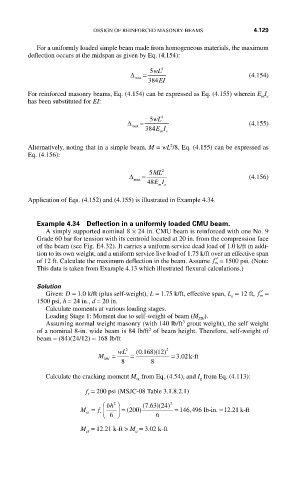
Example 4.34 Deflection in a uniformly loaded CMU beam.
A simply supported nominal 8 × 24 in. CMU beam is reinforced with one No. 9
Grade 60 bar for tension with its centroid located at 20 in. from the compression face
of the beam (see Fig. E4.32). It carries a uniform service dead load of 1.0 k/ft in addi-
tion to its own weight, and a uniform service live load of 1.75 k/ft over an effective span
of 12 ft. Calculate the maximum deflection in the beam. Assume ′ f = 1500 psi. (Note:
m
This data is taken from Example 4.13 which illustrated flexural calculations.)
Solution
Given: D = 1.0 k/ft (plus self-weight), L = 1.75 k/ft, effective span, L = 12 ft, ′ f =
m
e
1500 psi, h = 24 in., d = 20 in.
Calculate moments at various loading stages.
Loading Stage 1: Moment due to self-weight of beam (M ).
SW
3
Assuming normal weight masonry (with 140 lb/ft grout weight), the self weight
2
of a nominal 8-in. wide beam is 84 lb/ft of beam height. Therefore, self-weight of
beam = (84)(24/12) = 168 lb/ft
wL 2 (. )( 2
0 168 12)
M = = = 302. k-ft
SW
8 8
Calculate the cracking moment M from Eq. (4.54), and I from Eq. (4.113):
g
cr
f = 200 psi (MSJC-08 Table 3.1.8.2.1)
r
⎛ bh ⎞ (. ) ( 2
2
763 24)
.
M = f r ⎜ ⎟ = 200( ) = 146 496, l lb-in. ≈12 21 k-ft
cr ⎠
⎝ 6 6
M = 12.21 k-ft > M = 3.02 k-ft
cr a