
Page 268 - Design of Reinforced Masonry Structures
P. 268
DESIGN OF REINFORCED MASONRY BEAMS 4.131
The deflection due to live load is
2
(.
(
)
∆ = 5 ML 2 = 5 31 5 12) ( 12) 3 = 0 108 in.
.
L
48 EI 48 1050 7168)
(
)
(
8
me
The total beam deflection is sum of deflections in the three stages of loading. Thus,
∆ total = ∆ + ∆ + ∆ = 0.008 + 0.062 + 0.108 = 0.178 in. ≈ 0.18 in.
SD
SW
L
In case this beam were to support unreinforced masonry, the allowable deflection
would be
12 12
L ()()
e = = 024 in. > 018in. OK
.
.
600 600
However, no such restriction is specified in this problem.
Commentary: Note that as the beam cracks, the moment of inertia decreases progres-
sively as the applied moment increases. However, if the deflection is calculated using
I from Eq. (4.151) we would have
e
4
I = 0.5I = 0.5(8790) = 4395 in. which is less than I calculated above. Therefore,
g
e
e
4
use I = 4395 in. .
e
2
.
(
12
)
∆ = 5 ML 2 = 552 52 12() () 3 = . 0 295 in.
total
(
48 EI 48 1050))(4395 )
me
This deflection value is larger than L /600 limit (= 0.24 in.), but is less that L / 240
limit commonly prescribed for beams under service loads:
L 12 12()
= = 06 in.
.
240 240
However, no such deflections limits are prescribed in this problem.
Problems
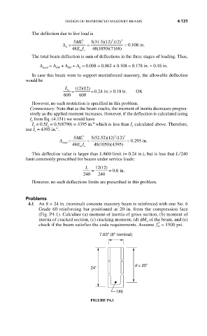
4.1 An 8 × 24 in. (nominal) concrete masonry beam is reinforced with one No. 6
Grade 60 reinforcing bar positioned at 20 in. from the compression face
(Fig. P4.1). Calculate (a) moment of inertia of gross section, (b) moment of
inertia of cracked section, (c) cracking moment, (d) fM of the beam, and (e)
n
check if the beam satisfies the code requirements. Assume ′ f = 1500 psi.
m
7.63" (8" nominal)
d = 20"
24"
1#6
FIGURE P4.1