
Page 251 - Design of Reinforced Masonry Structures
P. 251
4.114 CHAPTER FOUR
Maximum diaphragm shear V is computed by treating diaphragm as a simple beam, that
is, computed as beam reactions (which are transmitted at the top of shear walls):
V = wL / 2 (4.132)
The maximum unit diaphragm shear, v, is computed by dividing the maximum diaphragm
shear, V (= wL / 2) by the diaphragm depth (measured parallel to the diaphragm loads):
v = wL / 2d (4.133)
For design purposes, the diaphragm load w is to be computed for wind as well as seismic
loads as shown in Fig. 4.32, and the chord forces should be computed for the governing
diaphragm loads. According to equivalent static force procedures, diaphragm loads are
computed on the basis of tributary heights of walls or the building. In a typical reinforced
masonry building (symmetrical in plan and elevation), the chord forces so computed are
also the axial forces in the bond beams, which must resist them as axial loads. As alluded
to in the previous section, because of the reversible nature of lateral loads, any of the two
opposite sides of a diaphragm may be in tension. Because masonry is not permitted to resist
tensile forces, the entire tensile chord force, T, must be resisted by the reinforcement pro-
vided in each bond beam. The required amount of reinforcement can be calculated simply
by dividing the chord force by the yield stress in reinforcement:
T
s A = (4.134)
φ f
y
where f = 0.9 for a reinforced masonry member subjected to axial loads.
Application of these concepts discussion in this section is presented in Example 4.30.
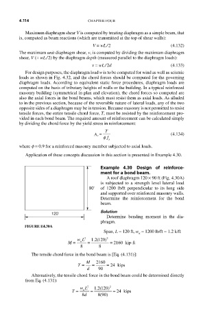
Example 4.30 Design of reinforce-
ment for a bond beam.
A roof diaphragm 120 × 90 ft (Fig. 4.30A)
is subjected to a strength level lateral load
90' of 1200 lb/ft perpendicular to its long side
and supported over reinforced masonry walls.
Determine the reinforcement for the bond
beam.
Solution
120'
Determine bending moment in the dia-
phragm.
FIGURE E4.30A
Span, L = 120 ft, w = 1200 lb/ft = 1.2 k/ft
u
M = wL 2 = 1 2 120) 2
.(
u
8 8 = 2160 kip-ft
The tensile chord force in the bond beam is [Eq. (4.131)]:
T = M = 2160 = 24 kips
d 90
Alternatively, the tensile chord force in the bond beam could be determined directly
from Eq. (4.131):
.(
T = wL 2 = 1 2 120) 2 = 24 kips
u
8 d 890)
(