
Page 250 - Design of Reinforced Masonry Structures
P. 250
DESIGN OF REINFORCED MASONRY BEAMS 4.113
L = Diaphragm span
T (tension)
d = Lever arm V V
Active
C
chords
(compression)
w = Diaphragm loading (lb/ft)
w lb/ft Diaphragm
force
d
C
L
d
T
V
Chord force
M lb-ft
Applied moment, M = 1/8 wL 2
resisting moment = C.d = T.d
2
M C = T = wL /8d
(a) (b)
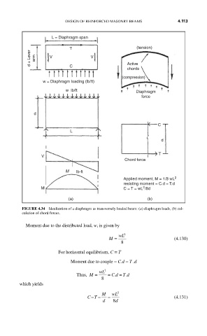
FIGURE 4.34 Idealization of a diaphragm as transversely loaded beam: (a) diaphragm loads, (b) cal-
culation of chord forces.
Moment due to the distributed load, w, is given by
M = wL 2 (4.130)
8
For horizontal equilibrium, C = T
Moment due to couple = C.d = T .d
Thus, M = wL 2 = . T d
Cd = .
8
which yields
CT== M = wL 2 (4.131)
d 8 d