
Page 253 - Design of Reinforced Masonry Structures
P. 253
4.116 CHAPTER FOUR
b
h d
A s
(a)
16" centers 24" centers
40" centers
32" centers
Block arrangements
for full height
steel using two cell
open end units.
(b)
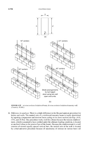
FIGURE 4.35 (a) cross section of reinforced beam, (b) cross section of reinforced masonry wall.
(Courtesy: NCMA.)
2. Difference in analyses: There is a slight difference in the flexural analysis procedure for
beams and walls. The neutral axis of a reinforced masonry beam is easily determined
by equating compression and tension forces acting on its cross section [see Eqs. (4.8),
(4.9), and (4.5b)]. This procedure works well for a beam because the tension reinforce-
ment, which is assumed to have yielded under the ultimate loading condition, is located
at one level (close to the tension face of the beam). Because the reinforcement in a wall
consists of several equally spaced vertical bars, the neutral axis of the wall is located
by a trial-and-error procedure because of uncertainty of stresses in various bars—all