
Page 276 - Design of Reinforced Masonry Structures
P. 276
DESIGN OF REINFORCED MASONRY BEAMS 4.139
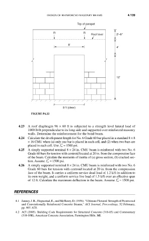
Top of parapet
R R
Roof level 2'–8''
8'
4'
12'
8 ft (clear)
FIGURE P4.22
4.23 A roof diaphragm 96 × 60 ft is subjected to a strength level lateral load of
1000 lb/ft perpendicular to its long side and supported over reinforced masonry
walls. Determine the reinforcement for the bond beam.
4.24 Calculate the development length for No. 6 Grade 60 bar placed in a standard 8 × 8
× 16 CMU when (a) only one bar is placed in each cell, and (2) when two bars are
placed in each cell. Use ′ f = 1500 psi.
m
4.25 A simply supported nominal 8 × 24 in. CMU beam is reinforced with two No. 6
Grade 60 bars for tension with centroid located at 20 in. from the compression face
of the beam. Calculate the moments of inertia of (a) gross section, (b) cracked sec-
tion. Assume ′ f = 1500 psi.
m
4.26 A simply supported nominal 8 × 24 in. CMU beam is reinforced with two No. 6
Grade 60 bars for tension with centroid located at 20 in. from the compression
face of the beam. It carries a uniform service dead load of 1.2 k/ft in addition to
its own weight, and a uniform service live load of 1.5 k/ft over an effective span
of 12 ft. Calculate the maximum deflection in the beam. Assume ′ f = 1500 psi.
m
REFERENCES
4.1 Janney, J. R., Hognestad, E., and McHenry, D. (1956). “Ultimate Flexural Strength of Prestressed
and Conventionally Reinforced Concrete Beams,” ACI Journal, Proceedings, 52 February,
pp. 601–620.
4.2 ACI (2005). Building Code Requirements for Structural Concrete (318-05) and Commentary
(318-05R), American Concrete Association, Farmington Hills, MI.