
Page 274 - Design of Reinforced Masonry Structures
P. 274
DESIGN OF REINFORCED MASONRY BEAMS 4.137
4.16 A simply supported clay brick beam is 9 in. wide and 24 in. deep with the ten-
sion reinforcement located at 20 in. from the top of the beam. The beam has an
effective span of 12 ft and carries a service live load of 1200 lb/ft in addition to
its own weight. Use ′ f = 2000 psi and Grade 60 steel. Determine the flexural
m
reinforcement required for this beam.
4.17 An 8-in. wide CMU lintel with a clear span of 12 ft has to carry a superimposed
dead load of 750 lb/ft and a live load of 800 lb/ft. Use ′ f = 1500 psi and Grade 60
m
reinforcement. Determine the depth of the lintel and the area of reinforcement.
The masonry would be built from normal weight CMU with a grout weight of
3
140 lb/ft . Assume that length of bearing on each support is 8 in.
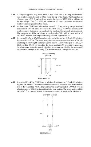
4.18 A nominal 8 × 24 in. CMU beam is reinforced with one No. 8 Grade 60 reinforc-
ing bar with d = 20 in. The beam is required to carry a service dead load of 1.0 k/ft
(including its self-weight) and a service live load of 1.0 k/ft over a span of 12 ft. ′ f =
m
1500 psi (Fig. P4.18) (a) Calculate the shear resistance V provided by masonry,
m
(b) what would be the increase in the shear resistance provided by the masonry if
the specified strength of masonry ′ f is increased from 1500 psi to 2000 psi.
m
7.63" (8" nominal)
d = 20"
24"
1#8
FIGURE P4.18
4.19 A nominal 10 × 40 in. CMU beam is reinforced with two No. 5 Grade 60 reinforc-
ing bars for tension. The centroid of reinforcement is located at 6 in. from the bot-
tom of the beam (Fig. P4.19). The beam carries a service load of 1200 lb/ft over an
effective span of 15 ft 8 in. in addition to its own weight. The grout unit weight is
3
140 lb/ft . ′ f = 1500 psi. Check if shear reinforcement is required for this beam.
m
9.63" (10" nominal)
40"
6"
2#5
FIGURE P4.19