
Page 276 - Design of Simple and Robust Process Plants
P. 276
262 Chapter 7 Optimization of an Integrated Complex of Process Plants
able at moderate temperatures in the specific situation where we are certain that
long-term, low-level heat is available at no cost. In general, they are applied in plants
with excess low level heat in the 90±115 C range.
For grass-root sites, the utility system and its levels have to be designed, and these
are discussed in the following section. Existing sites have their utility energy levels
selected, and process plants will accommodate the design of their internal system to
these levels. After these energy levels have been selected, they are difficult to modify
as the process equipment will be designed based on these temperature and pressure
levels. The installation of an intermediate level locally (at plant) is practiced, espe-
cially if heat is generated and consumed at a level which lies between the utility lev-
els.
The individuals plants should have made a pinch study and preliminary heat
exchange network design of their plant (IChemE, 1997). An exergy study might also
be useful to identify the situations where potentials for energy savings exist, to lower
the energy targets by process modifications (Kotas, 1995). The information needed
from the individual plant is as follows:
. The grand composite curves of the individual plants.
. The electrical power demand of the plant.
. The mechanical power demands of large processing machines potentially
available for steam turbine or gas turbine drive.
. The availability of a furnace to potentially install a gas turbine or gas motor in
front of (this will have an impact on the energy demand as this would exclude
an air preheat on the furnace).
. The variations in steam and power demand due to process variability like
capacity and catalyst aging, fouling.
A long-term energy forecast must be made for the site, based on projected projects.
The accumulated information of the plants and the forecast will be used for an
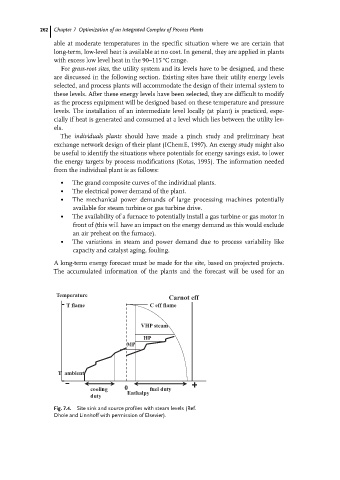
Temperature
Carnot eff
T flame C eff flame
VHP steam
HP
MP
T ambient
cooling 0 fuel duty
Enthalpy
duty
Fig. 7.4. Site sink and source profiles with steam levels (Ref.
Dhole and Linnhoff with permission of Elsevier).