
Page 385 - Design of Simple and Robust Process Plants
P. 385
372 Chapter 9 Operation Optimization
. The application of suboptimizations is to be decided during the control strat-
egy design as it has an impact on the model.
. Constraints to be modeled ± constraints are either handled in constraint con-
trollers often based on direct plant measurements, or they are modeled. This
differentiation must be made during the design of the control structure.
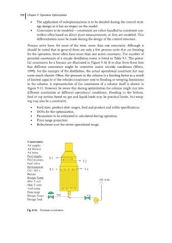
Process units have, for most of the time, more than one constraint. Although it
should be noted that in general there are only a few process units that are limiting
for the operation, these often have more than one active constraint. The number of
potential constraints of a simple distillation tower is listed in Table 9.1. The poten-
tial constraints for a furnace are illustrated in Figure 9.10. It is clear from these lists
that different constraints might be restrictive under variable conditions (White,
1999). For the example of the distillation, the actual operational constraint list may
seem much shorter. Often, the pressure in the column is a limiting factor as a result
of limited capacity of the reboiler/condenser next to flooding or weeping limitations
in the column. A representation of the constraints of a column itself is shown in
Figure 9.11. However, be aware that during optimization the column might run into
different constraints at different operational conditions. Flooding in the bottom,
feed or top section based on gas and liquid loads may be practical limits, but weep-
ing may also be a constraint:
. Feed slate, product slate ranges, feed and product and utility specifications.
. DOFs for the optimization.
. Parameters to be estimated or calculated during operation.
. Price range projection.
. Robustness over the entire operational range.
Constraints:
Air supply;
Air Blower
Air temp
Fuel supply;
T1
Fuel pressure
T2
Fuel valve
Environment
CO / NO x T3 T4
Burner
Design Temp
AIR intake
Skin T coil
Skin T conv
Arch temp
Furn.temp
Design Tconv Fuel
Design Trad
Fig. 9.10. Furnace constraints.