
Page 398 - Design of Simple and Robust Process Plants
P. 398
9.6 Project Methodology for Operation Optimization 385
Table 9.3. Example of a typical control configuration for simple distillation (see also Figure 9.12).
Basic control layer
CVs MVs
Feed flow Feed valve position
L top Distillate valve position
L bot Bottom valve position
Reflux flow Reflux valve position
Steam flow Steam valve position
Pressure Cooling water valve position
MBC layer
CVs MVs
Capacity maximization Feed flow set-point
Floating pressure Pressure set-point
Q bot Steam flow set-point
Q top* Reflux flow set-point
OO layer
CVs MVs
Profit Q bot set-point
Feed flow set-point optional
* Quality of top stream is seen as a constraint not subject to optimization
Recycle B
A
F
O.O
Recycle Y O.O
B
O.O Q s.p F Q F
T
MBC Q
O.O
Y P T Q MBC
F T T MBC
O.O Q
O.O
R
Q
Reactor
X
F
MBC or O.O
C
Reactants Products
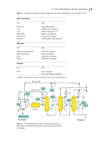
Fig. 9.13. Control hierarchy of reactor and finishing section
(level loops at overhead and bottoms and pressure control are
not shown).