
Page 399 - Design of Simple and Robust Process Plants
P. 399
386 Chapter 9 Operation Optimization
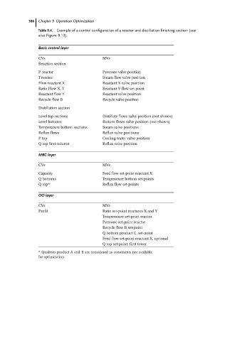
Table 9.4. Example of a control configuration of a reactor and distillation finishing section (see
also Figure 9.13).
Basic control layer
CVs MVs
Reaction section
P reactor Pressure valve position
T reactor Steam flow valve position
Flow reactant X Reactant X valve position
Ratio Flow X, Y Reactant Y flow set-point
Reactant flow Y Reactant valve position
Recycle flow B Recycle valve position
Distillation section
Level top sections Distillate flows valve position (not shown)
Level bottoms Bottom flows valve position (not shown)
Temperature bottom sections Steam valve positions
Reflux flows Reflux valve positions
P top Cooling water valve position
Q top first column Reflux valve position
MBC layer
CVs MVs
Capacity Feed flow set-point reactant X
Q bottoms Temperature bottom set-points
Q top* Reflux flow set-points
OO layer
CVs MVs
Profit Ratio set-point reactants X and Y
Temperature set-point reactor
Pressure set-point reactor
Recycle flow B set-point
Q bottom product C, set-point
Feed flow set-point reactant X, optional
Q top set-point, first tower
* Qualities product A and B are considered as constraints not available
for optimization