
Page 167 - Design of Solar Thermal Power Plants
P. 167
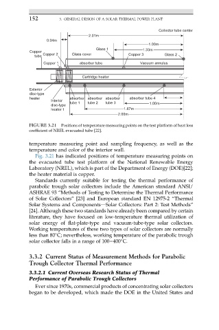
152         3. GENERAL DESIGN OF A SOLAR THERMAL POWER PLANT

                                                               Collector tube center
                                    2.01m
                   0.04m
                                                           1.00m
                                       Glass 1           1.33m
             Copper
               tube  Copper 2  Glass cover          Copper 3      Glass 2
                  Copper 1      absorber tube           Vacuum annulus

                                 Cartridge heater


             Exterior
             disc-type
             heater         absorber absorber absorber  absorber tube 4
                     Interior
                            tube 1  tube 2  tube 3          1.00m
                     disc-type
                     heater 1                     1.67m
                                               2.00m
            FIGURE 3.21  Positions of temperature measuring points on the test platform of heat loss
            coefficient of NREL evacuated tube [22].

            temperature measuring point and sampling frequency, as well as the
            temperature and color of the interior wall.
               Fig. 3.21 has indicated positions of temperature measuring points on
            the evacuated tube test platform of the National Renewable Energy
            Laboratory (NREL), which is part of the Department of Energy (DOE)[22];
            the heater material is copper.
               Standards currently suitable for testing the thermal performance of
            parabolic trough solar collectors include the American standard ANSI/
            ASHRAE 93 “Methods of Testing to Determine the Thermal Performance
            of Solar Collectors” [23] and European standard EN 12975-2 “Thermal
            Solar Systems and ComponentsdSolar Collectors: Part 2: Test Methods”
            [24]. Although these two standards have already been compared by certain
            literature, they have focused on low-temperature thermal utilization of
            solar energy of flat-plate-type and vacuum-tube-type solar collectors.
            Working temperatures of these two types of solar collectors are normally
            less than 80 C; nevertheless, working temperature of the parabolic trough

            solar collector falls in a range of 100e400 C.

            3.3.2 Current Status of Measurement Methods for Parabolic
            Trough Collector Thermal Performance
            3.3.2.1 Current Overseas Research Status of Thermal
            Performance of Parabolic Trough Collectors
               Ever since 1970s, commercial products of concentrating solar collectors
            began to be developed, which made the DOE in the United States and