
Page 225 - Design of Solar Thermal Power Plants
P. 225
208 3. GENERAL DESIGN OF A SOLAR THERMAL POWER PLANT
250.0 250.0
200.0 200.0
Simulation time = 1.00 h 150.0
Temperature /°C 100.0 100.0
150.0
50.0 50.0
0.0 0.0
0.0000 0.0833 0.1667 0.2500 0.3333 0.4167 0.5000 0.5833 0.6667 0.7500 0.8333 0.9167 1.0000
Thermal discharging time /h
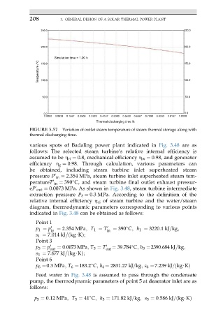
FIGURE 3.57 Variation of outlet steam temperature of steam thermal storage along with
thermal discharging time.
various spots of Badaling power plant indicated in Fig. 3.48 are as
follows: The selected steam turbine’s relative internal efficiency is
assumed to be h ri ¼ 0.8, mechanical efficiency h m ¼ 0.98, and generator
efficiency h g ¼ 0.98. Through calculation, various parameters can
be obtained, including steam turbine inlet superheated steam
pressure P in ¼ 2.354 MPa, steam turbine inlet superheated steam tem-
0
peratureT in ¼ 390 C, and steam turbine final outlet exhaust pressur-
0
eP out ¼ 0.0073 MPa. As shown in Fig. 3.48, steam turbine intermediate
0
extraction pressure P b ¼ 0.3 MPa. According to the definition of the
relative internal efficiency h ci of steam turbine and the water/steam
diagram, thermodynamic parameters corresponding to various points
indicated in Fig. 3.48 can be obtained as follows:
Point 1
p 1 ¼ p 0 ¼ 2:354 MPa; T 1 ¼ T 0 ¼ 390 C; h 1 ¼ 3220:1kJ=kg;
in in
s 1 ¼ 7:014 kJ ðkg$KÞ;
Point 3
p 3 ¼ p 0 ¼ 0:0073MPa; T 3 ¼ T 0 ¼ 39:784 C; h 3 ¼2390:684 kJ kg;
out out
s 3 ¼ 7:677 kJ ðkg$KÞ;
Point 6
p 6 ¼0:3MPa; T 6 ¼183:2 C; h 6 ¼ 2831:27 kJ=kg; s 6 ¼7:239 kJ=ðkg$KÞ
Feed water in Fig. 3.48 is assumed to pass through the condensate
pump, the thermodynamic parameters of point 5 at deaerator inlet are as
follows:
p 5 ¼ 0:12 MPa; T 5 ¼ 41 C; h 5 ¼ 171:82 kJ=kg; s 5 ¼ 0:586 kJ=ðkg$KÞ