
Page 181 - Designing Autonomous Mobile Robots : Inside the Mindo f an Intellegent Machine
P. 181
Chapter 11
The correction we will actually make for each axis is calculated as it was for azimuth,
by multiplying the full implied correction (error) by the Q factor for the whole fit.
x = – (Q * E ) (Equation 11.13)
COR FITx x
And
y COR = – (Q FITy * E ) (Equation 11.14)
y
Assume that this robot had begun this whole process with significant uncertainty for
both azimuth and position, and had suddenly started to get good images of these col-
umns. It would not have corrected all of its axes at the same rate.
At first, the most improvement would be in the azimuth (the most important degree
of freedom), then in the lateral position, and then, somewhat more slowly, the
longitudinal position. This would be because the corrections in the azimuth would
reduce the azimuth uncertainty, which would increase the observation quality for
the position measurements. However, we have only discussed how uncertainty
grows, not how it is reduced.
Other profiles
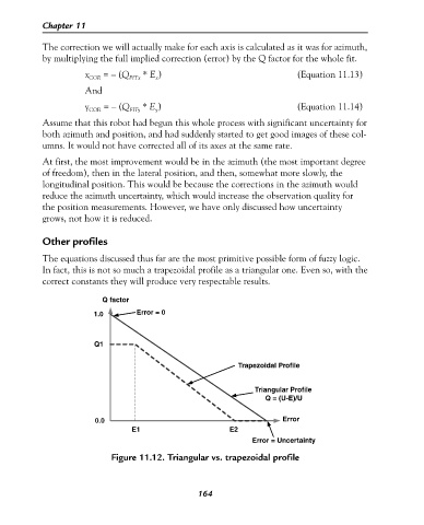
The equations discussed thus far are the most primitive possible form of fuzzy logic.
In fact, this is not so much a trapezoidal profile as a triangular one. Even so, with the
correct constants they will produce very respectable results.
Q factor
1.0 Error = 0
Q1
Trapezoidal Profile
Triangular Profile
Q = (U-E)/U
0.0 Error
E1 E2
Error = Uncertainty
Figure 11.12. Triangular vs. trapezoidal profile
164