
Page 198 - Digital Analysis of Remotely Sensed Imagery
P. 198
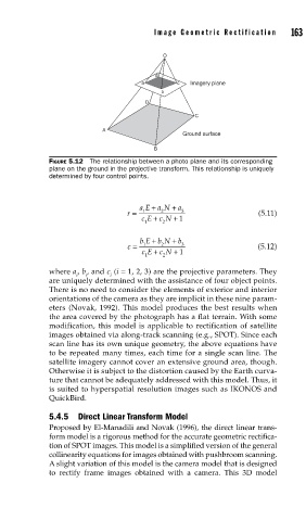
Image Geometric Rectification      163

                                            O

                                          d
                                       a        c  Imagery plane
                                            b
                                        D
                                                    C
                             A
                                                 Ground surface
                                          B
               FIGURE 5.12  The relationship between a photo plane and its corresponding
               plane on the ground in the projective transform. This relationship is uniquely
               determined by four control points.


                                      aE +  a N +  a
                                   r =  1   2    3                  (5.11)
                                          +
                                       cE c N + 1
                                        1   2
                                         +
                                      bE b N +  b
                                   c =  1   2    3                  (5.12)
                                          +
                                       cE c N + 1
                                        1   2
               where a , b , and c  (i = 1, 2, 3) are the projective parameters. They
                      i  i     i
               are uniquely determined with the assistance of four object points.
               There is no need to consider the elements of exterior and interior
               orientations of the camera as they are implicit in these nine param-
               eters (Novak, 1992). This model produces the best results when
               the area covered by the photograph has a flat terrain. With some
               modification, this model is applicable to rectification of satellite
               images obtained via along-track scanning (e.g., SPOT). Since each
               scan line has its own unique geometry, the above equations have
               to be repeated many times, each time for a single scan line. The
               satellite imagery cannot cover an extensive ground area, though.
               Otherwise it is subject to the distortion caused by the Earth curva-
               ture that cannot be adequately addressed with this model. Thus, it
               is suited to hyperspatial resolution images such as IKONOS and
               QuickBird.

               5.4.5  Direct Linear Transform Model
               Proposed by El-Manadili and Novak (1996), the direct linear trans-
               form model is a rigorous method for the accurate geometric rectifica-
               tion of SPOT images. This model is a simplified version of the general
               collinearity equations for images obtained with pushbroom scanning.
               A slight variation of this model is the camera model that is designed
               to rectify frame images obtained with a camera. This 3D model