
Page 126 - Distillation theory
P. 126
P1: FCH/FFX P2: FCH/FFX QC: FCH/FFX T1: FCH
0521832772c04 CB644-Petlyuk-v1 June 11, 2004 17:49
100 Trajectories of Thermodynamically Reversible Distillation
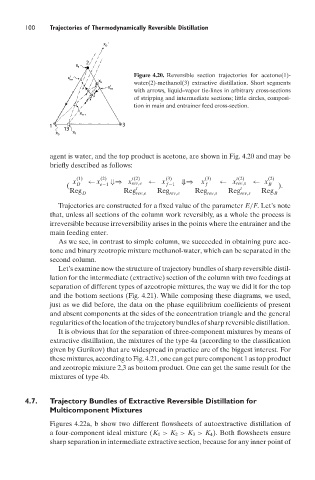
Figure 4.20. Reversible section trajectories for acetone(1)-
water(2)-methanol(3) extractive distillation. Short segments
with arrows, liquid–vapor tie-lines in arbitrary cross-sections
of stripping and intermediate sections; little circles, composi-
tion in main and entrainer feed cross-section.
agent is water, and the top product is acetone, are shown in Fig. 4.20 and may be
briefly described as follows:
(1) (2) t(2) (3) (3) t(2) (2)
x ← x ⇓⇒ x rev,e ← x ⇓⇒ x ← x rev,s ← x
( D e−1 t f −1 f t B ).
Reg D Reg rev,e Reg rev,e Reg rev,s Reg rev,s Reg B
Trajectories are constructed for a fixed value of the parameter E/F. Let’s note
that, unless all sections of the column work reversibly, as a whole the process is
irreversible because irreversibility arises in the points where the entrainer and the
main feeding enter.
As we see, in contrast to simple column, we succeeded in obtaining pure ace-
tone and binary zeotropic mixture methanol-water, which can be separated in the
second column.
Let’s examine now the structure of trajectory bundles of sharp reversible distil-
lation for the intermediate (extractive) section of the column with two feedings at
separation of different types of azeotropic mixtures, the way we did it for the top
and the bottom sections (Fig. 4.21). While composing these diagrams, we used,
just as we did before, the data on the phase equilibrium coefficients of present
and absent components at the sides of the concentration triangle and the general
regularities of the location of the trajectory bundles of sharp reversible distillation.
It is obvious that for the separation of three-component mixtures by means of
extractive distillation, the mixtures of the type 4a (according to the classification
given by Gurikov) that are widespread in practice are of the biggest interest. For
these mixtures, according to Fig. 4.21, one can get pure component 1 as top product
and zeotropic mixture 2,3 as bottom product. One can get the same result for the
mixtures of type 4b.
4.7. Trajectory Bundles of Extractive Reversible Distillation for
Multicomponent Mixtures
Figures 4.22a, b show two different flowsheets of autoextractive distillation of
a four-component ideal mixture (K 1 > K 2 > K 3 > K 4 ). Both flowsheets ensure
sharp separation in intermediate extractive section, because for any inner point of