Page 303 - Distillation theory
P. 303

P1: JPJ/FFX  P2: FCH/FFX  QC: FCH/FFX  T1: FCH
            0521820928c08  CB644-Petlyuk-v1                                                      June 11, 2004  20:20


                                8.3 Thermodinamically Improved and Thermally Integrated Separation  277


                                                                  C 1


                                                           T 4
                                                          y F4
                                                   T 3
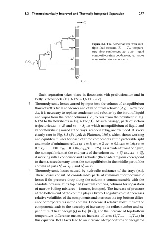
                                                                       Figure 8.4. The demethanizer with mul-
                                                                       tiple feed streams. T 1 ÷ T 4 , tempera-
                                                          x F3
                                                                       ture since condencers, x F1 ÷ x F3 , liquid
                                            T 2
                                                                       compositionssincecondencers; y F4 ,vapor
                                                          x F2         composition since condencer.
                                C ,C + T 1
                                 1     2
                                                          x F1

                                                                  C 2 +


                                        Such separation takes place in flowsheets with prefracionator and in
                                      Petlyuk flowsheets (Fig. 6.12c ÷ f,6.13 α ÷ c).
                                  3.  Thermodynamic losses caused by input into the column of unequilibrium
                                      flows of reflux from condenser and of vapor from reboiler (	 3 ). To exclude
                                      	 3 , it is necessary to replace condenser and reboiler by the input of liquid
                                      and vapor from the other columns (i.e., to turn from the flowsheet in Fig.
                                      6.12d to the flowsheets in Fig. 6.12c,e,f). At such passage, parts of section
                                                       1
                                                                  1
                                      trajectories x D → S and x B → S , at which nonequilibrium of liquid and
                                                      r           s
                                      vapor flows being mixed at the trays is especially big, are excluded. It is very
                                      clearly seen in Fig. 8.5 (Petlyuk & Platonov, 1965), which shows working
                                      and equilibrium lines for each of three components at the preferable split
                                      and mode of minimum reflux (α 13 = 5; α 23 = 2; x F1 = 0.1; x F2 = 0.6; x F3 =
                                      0.3; x B1 = 0.0001; x D3 = 0.0004; L min /F = 0,25). As is evident from the figure,
                                                                                        1
                                                                                                    1
                                      the nonequilibrium at the end parts of the column x D → S and x B → S ,
                                                                                                   s
                                                                                        r
                                      if working with a condenser and a reboiler (the shaded regions correspond
                                      to them), exceeds many times the nonequilibrium in the middle part of the
                                                                 1
                                                     1
                                      column at parts S → x f−1 and S → x f .
                                                                 s
                                                    r
                                  4.  Thermodynamic losses caused by hydraulic resistance of the trays (	 4 ).
                                      These losses consist of considerable parts of summary thermodynamic
                                      losses if the pressure drop along the column is commensurable with the
                                      absolute pressure at its top end (vacuum columns, columns for separation
                                      of narrow-boiling mixtures – isomers, isotopes). The increase of pressure
                                      at the bottom end of the column plays a twofold negative role: it decreases
                                      relative volatilities of the components and increases the top-bottom differ-
                                      ence of temperatures in the column. Decrease of relative volatilities of the
                                      components leads to the necessity of increasing the reflux number and ex-
                                      penditure of heat energy (Q in Eq. [8.2]), and the increase of top-bottom
                                      temperature difference means an increase of term (1/T con − 1/T reb )in
                                      this equation. Both facts lead to an increase of expenditures of energy for
   298   299   300   301   302   303   304   305   306   307   308