Page 304 - Distillation theory
P. 304

P1: JPJ/FFX  P2: FCH/FFX  QC: FCH/FFX  T1: FCH
            0521820928c08  CB644-Petlyuk-v1                                                      June 11, 2004  20:20


                        278    Synthesis of Separation Flowsheets

                                    y i
                                  .
                                  10                 t                     x D
                                                     x                       1,2
                                                      ,
                               a)  0.9               s 2   t         b)
                                                          x
                                  0.8                 c b  r 2 ,          a
                                  0.7    x D  1 ,  =  x  3 , B  d           x t r
                                  0.6                 a                   b
                                                                      1,2,3
                                  0.5                                       x F
                                     x  b   a                             c
                                  0.4  F  1 ,          x  =  x  =  x
                                           t   d         2 , F  2 , D  2 , B  x t
                                  0.3     x                                  s
                                     c     r 1 ,                          d
                                  0.2   x  3 , F  x  t
                                                s 3,
                                  0.1        c
                                          b                                  2,3
                                   0                          x i          x B
                                                             .
                                      0.1 0.2 0.3 0.4 0.5 0.6 0.7 0.8 0.9  10
                                    x =  x  t
                                     t
                                     s 1,  r 3,
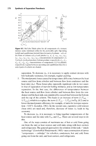
                               Figure 8.5. McCabe-Thiele plots for all components of a ternary
                               mixture under minimum reflux for the preferable split. Operating
                               (solid) and equilibrium (dotted) lines for parts of column − a,b,c,d.
                                                                 t  t
                               (b) Parts of column a,b,c,d and pinches x F, x , x . x F,1, x F,2, x F,3,
                                                                r  s
                               x D,1, x D,2, x D,3, x B,1, x B,2, x B,3 , concentrations of components 1, 2,
                                                                          t
                                                                             t
                               3 in feed, overhead product, bottom product, respectively; x , x ,
                                                                          r,1  r,2
                                          t
                                      t
                                   t
                                t
                               x , x , x , x , concentrations of components 1,2,3 in pinches,
                               r,3  s,1  s,2  s,3
                               respectively; regions between operating and equilibrium lines for a
                               and d parts of column are shaded.
                                     separation. To decrease 	 4 , it is necessary to apply contact devices with
                                     low hydraulic resistance, for example, regular packing.
                                 5.  Thermodynamic losses caused by temperature difference between the heat
                                     source and flow from reboiler and between flow from condenser and the
                                     heat sink (	 5 ). These losses play especially significant role in two cases:
                                     in that of separation of narrow-boiling mixtures, and at low-temperature
                                     separation. In the first case, the differences of temperatures between
                                     the heat source and flow from reboiler and between flow from the con-
                                     denser and the heat sink can considerably exceed that between the bottom
                                     and the top of the column. This leads to an increase of term (1/T sink −
                                     1/T sours ), which is to replace the term (1/T con − 1/T reb ) in Eq. (8.2) and to
                                     lower thermodynamic efficiency, for example, of units for isotopes separa-
                                     tion – 0,01% (London, 1961). In the second case, expensive cold sources
                                     (heat sink) are used and, therefore, decrease of losses 	 5 leads to big
                                     economy.
                                       To decrease 	 5 , it is necessary to bring together temperatures of the
                                     heat source and the sink with T reb and T con . There are several ways to do
                                     this.
                                       One of the ways consists of maximum use of hot or cold flows going
                                     out from the unit as heat sources and cold sinks along with heat carriers
                                     and refrigerants. The general approach to the solution of this task –“pinch
                                     technology” (Linnhoff & Hindermarsh, 1983) – uses construction of curves
                                     “temperature – enthalpy” for reboilers, condensers, hot and cold flows
                                     going out from the unit, and heat carriers, and refrigerants.
   299   300   301   302   303   304   305   306   307   308   309