Page 183 - Distributed model predictive control for plant-wide systems
P. 183

Networked Distributed Predictive Control with Information Structure Constraints  157


                           Preheating  Zone   Heating Zone   Soaking Zone
                                                                           Thermometer
                                                                            Burner
                                       ⊕              ⊕              ⊕
                Billet

                Charging                                                  Discharging

                                       ⊕              ⊕              ⊕


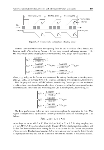
                            Figure 7.13  Structure of a walking beam reheating furnace


               Thermal transmission is carried through only from the end to the head of the furnace, the
             dynamic model of the reheating furnace is derived using material and energy balances [110].
             The linear model of the reheating furnace for networked MPC design can be described as

                        ⎧        0.002757
                         y (s)=
                                           1
                        ⎪ 1               u (s)
                                s + 0.00572
                        ⎪
                        ⎪        0.003983  −32.8s       0.001009  −52.5s
                        ⎨ y (s)=           e    u (s)+           e    y (s)
                          2
                                                 2
                                                                       1
                                s + 0.001891          s + 0.001907
                        ⎪
                        ⎪        0.001088  −33.2s       0.003224
                        ⎪y (s)=            e    u (s)+           y (s)
                                                                  2
                                                 3
                          3
                        ⎩       s + 0.003857          s + 0.004634
             where y , y and y are the furnace temperatures of the soaking, heating and preheating zones,
                           3
                   1
                      2
             and u , u and u are fuel feed flows of the soaking, heating and preheating zones, respectively.
                 1
                         3
                    2
               With the proposed networked MPC scheme, the reheating furnace process can be decom-
             posed into three subsystems, they are subsystems of soaking zone (the first subsystem), heating
             zone (the second subsystem) and preheating zone (the third subsystem), respectively, i.e.
                                   ⎧        0.002757
                                    y (s)=
                                   ⎪ 1               u (s)
                                                      1
                                           s + 0.00572
                                   ⎪
                                   ⎪        0.003983   −32.8s
                                   ⎨ y (s)=           e    u (s)
                                     2
                                                            2
                                           s + 0.001891
                                   ⎪
                                   ⎪        0.001088   −33.2s
                                   ⎪y (s)=            e    u (s)
                                                            3
                                     3
                                   ⎩       s + 0.003857
               The local performance index for each subsystem employs the expression in (36), With
             regards to neighborhood optimization, the new performance index for each subsystem is as
             follows:
                                       J (k)= J (k)+ J (k)+ J (k)
                                                          3
                                        i
                                              1
                                                    2
             each subsystem are set with P = 30, M = 10, Q = 10, R = 2(i = 1, 2, 3), using sampling time
                                                  i
                                                         i
             of 1 min. MATLAB-based simulation results (Figure 7.14) show the furnace temperatures and
             the fuel feed flows of three zones running for 4 h. It can be seen that the furnace temperatures
             of three zones in this distributed structure follow their set-points (shown as the dotted lines in
             the figure) satisfactorily and that the interaction between the channels is effectively reduced.
   178   179   180   181   182   183   184   185   186   187   188