
Page 84 - Drilling Technology in Nontechnical Language
P. 84
Chapter 3 – DRILLING A LAND EXPLORATION WELL 75
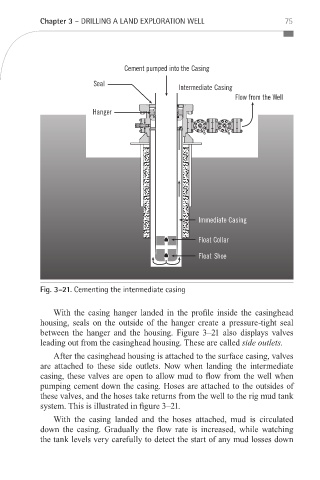
Fig. 3–21. Cementing the intermediate casing
With the casing hanger landed in the profile inside the casinghead
housing, seals on the outside of the hanger create a pressure-tight seal
between the hanger and the housing. Figure 3–21 also displays valves
leading out from the casinghead housing. These are called side outlets.
After the casinghead housing is attached to the surface casing, valves
are attached to these side outlets. Now when landing the intermediate
casing, these valves are open to allow mud to flow from the well when
pumping cement down the casing. Hoses are attached to the outsides of
these valves, and the hoses take returns from the well to the rig mud tank
system. This is illustrated in figure 3–21.
With the casing landed and the hoses attached, mud is circulated
down the casing. Gradually the flow rate is increased, while watching
the tank levels very carefully to detect the start of any mud losses down
_Devereux_Book.indb 75 1/16/12 2:07 PM