
Page 129 - Dust Explosions in the Process Industries
P. 129
102 Dust Explosions in the Process Industries
SUPPRESSOR
PRESSURE RISE
SUPPRESSANT
IGNITION
5-10 bar lgl
- UNSUPPRESSED
-
IF ENCLOSURE
d 0.4 __________ 0.35 -r _______.
0.2
v)
2 '"0 20 60 100 0 20 60 100 0 20 60 100 0 20 60 100 0 20 60 100
E
1. Ianltlon 2. Pressure rise detector 3. Suppressant lnjectlon 4. Suppre~sanl ln]ectlon 5. Suppresslon
%memo: o ma triggers rupprosrorr Starts CO"ll""84 complete
Pielours: 0 bar (g) %me: 20 ms Time 30 ms Tme: 50 ms Time: 80 ms
Pressure: 0.035 bar (g) Pressure: 0.085 bar (e) Pressure: 0.2 bar (9) Pressure: 0.15 bar 19)
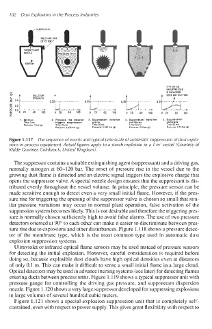
Figure 1.1 17 The sequence of events and typical time scale of automatic suppression of dust explo-
sions in process equipment. Actual figures apply to a starch explosion in a 1 m3 vessel (Courtesy of
Kidde-Craviner, Colnbrock, United Kingdom).
The suppressor contains a suitable extinguishing agent (suppressant) and a driving gas,
normally nitrogen at 60-120 bar. The onset of pressure rise in the vessel due to the
growing dust flame is detected and an electric signal triggers the explosive charge that
opens the suppressor valve. A special nozzle design ensures that the suppressant is dis-
tributed evenly throughout the vessel volume. In principle, the pressure sensor can be
made sensitive enough to detect even a very small initial flame. However, if the pres-
sure rise for triggering the opening of the suppressor valve is chosen so small that sim-
ilar pressure variations may occur in normal plant operation, false activation of the
suppression system becomes likely. This is not desirable and therefore the triggering pres-
sure is normally chosen sufficiently high to avoid false alarms. The use of two pressure
detectors oriented at 90" to each other can make it easier to discriminate between pres-
sure rise due to explosions and other disturbances. Figure 1.118 shows a pressure detec-
tor of the membrane type, which is the most common type used in automatic dust
explosion suppression systems.
Ultraviolet or infrared optical flame sensors may be used instead of pressure sensors
for detecting the initial explosion. However, careful consideration is required before
doing so, because explosible dust clouds have high optical densities even at distances
of only 0.1 m. This can make it difficult to sense a small initial flame in a large cloud.
Optical detectors may be used in advance inerting systems (see later) for detecting flames
entering ducts between process units. Figure 1.119 shows a typical suppressor unit with
pressure gauge for controlling the driving gas pressure, and suppressant dispersion
nozzle. Figure 1.120 shows a very large suppressor developed for suppressing explosions
in large volumes of several hundred cubic meters.
Figure 1.121 shows a special explosion suppression unit that is completely self-
contained, even with respect to power supply. This gives great flexibility with respect to