
Page 270 - Dust Explosions in the Process Industries
P. 270
242 Dust Explosions in the Process Industries
LID NOZZLE
CYLINDER
-COAL DUST
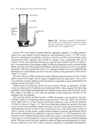
Figure 3.30 "Whirling" chamber for fluidizing the
dust sample and subsequently forcing the dense
dudair suspension through a series of parallel
nozzle holes (From Helwig, 1965).
Siwek (1977) developed a smaller spherical apparatus capable of yielding approxi-
mately the same degree of dust dispersion and turbulence as the 1 m3 IS0 vessel.
However, obtaining an acceptable correlation with the 1m3IS0 vessel required a large
experimental effort, starting with a bomb of volume 5 liter, continuing with one of
volume 10 liter, and ultimately finishing up with the final bomb of 20 liter. In particu-
lar, it was necessary to investigate a range of different dispersion nozzle systems before
finally arriving at one that produced turbulence and dust dispersion levels in acceptable
agreement with those generated in the 1 m3 standard chamber. It is not surprising that
the dispersion system finally arrived at was very similar to the perforated U-tube system
of the 1 m3vessel.
However, Siwek (1988) introduced a quite different dispersal nozzle for the 20 liter
sphere, based on the high-velocity impact of agglomerates on target plates. This system
was claimed to produce degrees of dust dispersion comparableto those generated by the
original nozzle (see Figure 7.58).
Following the development of the 20 liter vessel by Siwek, an alternative 20 liter
vessel was proposed by Cashdollar and Hertzberg (1985). They mention the interesting
possibility of inserting interchangeabledust dispersion units at the bottom of their vessel.
This makes it possible to work with the intensity of dust dispersion relevant for the
problem to be investigated.
The Institute of Iron and Steel in Kiev, USSR, developed a dust dispersion unit par-
ticularly suitable for dispersing cohesive metal powders. The unit, which was mounted
at the upper end of a 4 liter vertical cylindrical explosion vessel of internal diameter
110 mm, is shown in Figure 3.31. The basic philosophy behind this design is the same
as for several of the methods already discussed. The dust cloud, after having been ini-
tially dispersed by the air blast in the conventional way, is forced through a system of
narrow nozzles at high speed, causing further breakup of particle agglomerates before
the cloud is admitted to the explosion vessel (see Section 3.7). The concentration dis-
tribution of the resulting transient dust cloud in the vessel, as a function of time and posi-
tion in space, was investigated by means of a special gravimetric concentration sampling
probe. The dust clouds were also studiedby means of high-speed photographyby replac-
ing the explosion vessel with a glass container. Generally, a reasonably homogeneous