
Page 271 - Dust Explosions in the Process Industries
P. 271
Generation of Explosible Dust Clouds 243
10 9 8 7 6
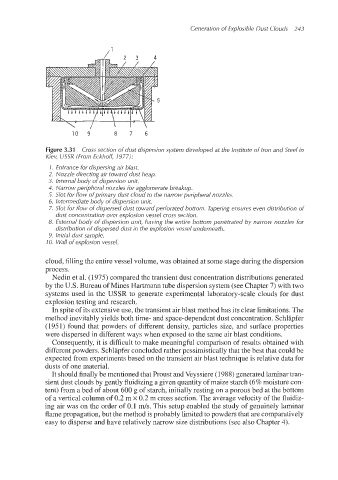
Figure 3.31 Cross section of dust dispersion system developed at the Institute of iron and Steel in
Kiev, USSR (From Eckhoft 1977):
1. Entrance for dispersing air blast.
2. Nozzle directing air toward dust heap.
3. Internal body of dispersion unit.
4. Narrow peripheral nozzles for agglomerate breakup.
5. Slot for flow of primary dust cloud to the narrow peripheral nozzles.
6. Intermediate body of dispersion unit.
7. Slos for flow of dispersed dust toward perforated bottom. Tapering ensures even distribution of
dust concentration over explosion vessel cross section.
8. External body of dispersion unit, having the entire bottom penetrated by narrow nozzles for
distribution of dispersed dust in the explosion vessel underneath.
9. Initial dust sample.
10. Wall of explosion vessel.
cloud, filling the entire vessel volume, was obtained at some stage during the dispersion
process.
Nedin et al. (1975) compared the transient dust concentration distributions generated
by the U.S. Bureau of Mines Hartmann tube dispersion system (see Chapter 7) with two
systems used in the USSR to generate experimental laboratory-scale clouds for dust
explosion testing and research.
In spite of its extensive use, the transient air blast method has its clear limitations. The
method inevitably yields both time- and space-dependent dust concentration. Schlapfer
(1951) found that powders of different density, particles size, and surface properties
were dispersed in different ways when exposed to the same air blast conditions.
Consequently, it is difficult to make meaningful comparison of results obtained with
different powders. Schlapfer concluded rather pessimistically that the best that could be
expected from experiments based on the transient air blast technique is relative data for
dusts of one material.
It should finally be mentioned that Proust and Veyssiere (1988) generated laminar tran-
sient dust clouds by gently fluidizing a given quantity of maize starch (6% moisture con-
tent) from a bed of about 600 g of starch, initially resting on a porous bed at the bottom
of a vertical column of 0.2 m x 0.2 m cross section. The average velocity of the fluidiz-
ing air was on the order of 0.1 m/s. This setup enabled the study of genuinely laminar
flame propagation, but the method is probably limited to powders that are comparatively
easy to disperse and have relatively narrow size distributions (see also Chapter 4).