
Page 350 - Dust Explosions in the Process Industries
P. 350
Propagation of Flames in Dust Clouds 3 19
Buksowicz, Klemens, and Wolanski (1982) and Klemens and Wolanski (1986) describe
experiments with a lignite dust of 52% volatiles, 6% ash, and <75 pm particle size, in a
1.2 m long vertical duct of rectangular cross section of width 88 mm and depth 35 mm.
The duct was closed at the top and open at the bottom. Dust was fed at the top by a cal-
ibrated vibratory feeder yielding the desired dust concentration. The ignition source (an
electric spark of a few J energy or a gas burner flame) was located near the open bottom
end. Flame propagation and flame structure were recorded through a pair of opposite
80 mm x 80 mm glass windows. Diagnostic methods included Mach-Zehnder interfer-
ometry, high-speed framing photography, and high-frequency response electrical resist-
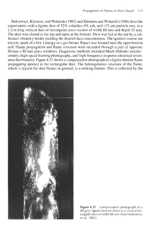
ance thermometry. Figure 4.3 1 shows a compensation photograph of a lignite dudair flame
propagating upward in the rectangular duct. The heterogeneous structure of the flame,
which is typical for dust flames in general, is a striking feature. This is reflected by the
Figure 4.31 Compensation photograph of a
80 g/m3 lignite dust/air flame in a vertical rec-
tangular duct of width 88 mm (From Buksowicz
et a/., 1982).