
Page 446 - Dust Explosions in the Process Industries
P. 446
Ignition of Dust Clouds and Dust Deposits 413
POLY ACRYLON /-
/
/
ELECTRIC ARC FORMATION
-1
6 IN AIR AT NORMAL
u CONDITIONS IMPOSSIBLE
CT
c BEYOND THIS LINE
U
w
-.I
W
10-7 10 -6 IO-^ 10-4 10-3 10-2
SPARK DISCHARGE DURATION [SI
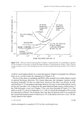
Figure 5.1 8 Minimum electric spark ignition energies of approximately 5% probability of ignition
for four powders as functions of spark discharge duration, as determined by Parker (1 985). Electric
energy ofsparks is from CMI-spark generator, as a function of spark discharge duration (From Eckhofi,
1975).
could be varied independently in a controlled manner. Parker investigated four different
dusts in air, and the results are summarized in Figure 5.18.
For two of the dusts (lycopodium and PAN), there seemed to be a fairly distinct region
of optimal discharge durations. For shorter durations, the minimum ignition energy
increased markedly. For the two other dusts, however, this effect was absent. As indi-
cated in Figure 5.18, an optimum discharge duration line may be drawn through the results
for the four powders. For comparison the spark duratiodspark energy characteristic of
the CMI discharge circuit (see Chapter 7) has also been included in Figure 5.18. This
refers to an R-C-IL circuit of inductance L 2 1mH, for which the discharge will normally
be a damped oscillation. The discharge time may then be defined as the time needed for
the exponential damping factor to decrease to 1% of the initial maximum value. The dis-
charge duration then equals
t = 9.2 a Ll R (5.28)
which corresponds to equation (5.27) for the overdamped case.