
Page 448 - Dust Explosions in the Process Industries
P. 448
Ignition of Dust Clouds and Dust Deposits 4 15
5.3.4
INFLUENCE OF SOME FURTHER PARAMETERS ON THE MINIMUM
IGNITION ENERGY OF DUST CLOUDS
5.3.4.1
Movermenflurbulence of Dust Clouds
The marked increase of the minimum ignition energy for premixed gases with the tur-
bulence intensity of the gas mixture has been demonstratedby various workers, includ-
ing Bailal and Lefebvre (1977) and Bradley and Lung (1987). One would expect a
similar influence of the turbulence intensity of dust clouds on their minimum ignition
energies, as indicated by Figure 1.40in Chapter 1. Figure 5.20 gives some supplemen-
tary data by Smielkow and Rutkowski (1971).
I I I I I I
0 10 20 30
VELOCITY OF OUST/AIR JET Im/sl
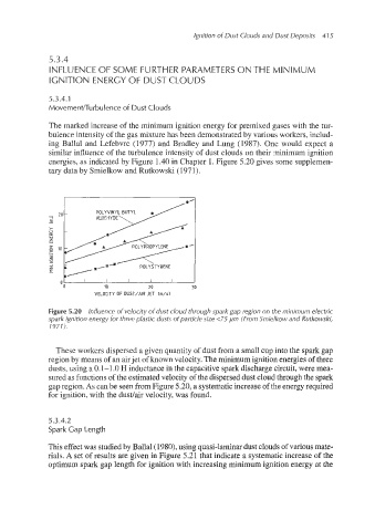
Figure 5.20 Influence of velocity of dust cloud through spark gap region on the minimum electric
spark ignition energy for three plastic dusts of particle size <75 pm (From Smie!kow and Rutkowski,
19711.
These workers dispersed a given quantity of dust from a small cup into the spark gag
region by means of an airjet of known velocity. The minimum ignition energiesof three
dusts, using a 0.1-1 .O H inductance in the capacitive spark discharge circuit, were mea-
sured as functions of the estimatedvelocity of the dispersed dust cloud through the spark
gap region. As can be seen from Figure 5.20, a systematic increaseof the energy required
for ignition, with the dustlair velocity, was found.
5.3.4.2
Spark Gap Length
This effect was studied by Ballal(1980), using quasi-laminardust clouds of various mate-
rials. A set of results are given in Figure 5.21 that indicate a systematic increase of the
optimum spark gap length for ignition with increasing minimum ignition energy at the