
Page 563 - Dust Explosions in the Process Industries
P. 563
530 Dust Explosions in the Process Industries
30% barium peroxide. It is activated by an electric fuse head. The ignitor is located at
the geometric center of the explosion chamber. Two pressure transducers, linked to a
recorder, are fitted to measure the explosion chamber pressure development.
The way of determining the maximum explosion pressure is similar to that of the
Hartmann bomb test, and Figures 7.52 and 7.53 also apply to the 1 m3 test. However,
due to the comparatively large size of the experiment, the amount of dust and the time
required per experiment limit the number of tests that are normally performed.
Maximum explosion pressures measured with this apparatus would be expected to be
relatively close to the theoretical maximum adiabatic pressures. Data for a range of
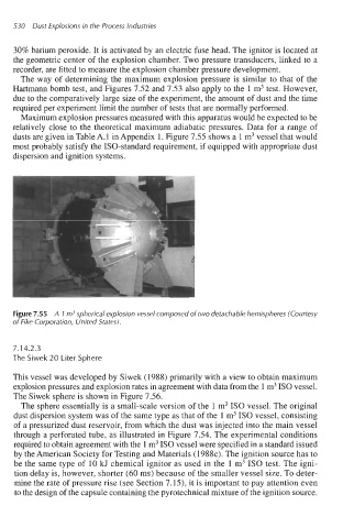
dusts are given in Table A. 1 in Appendix 1. Figure 7.55 shows a 1 m3 vessel that would
most probably satisfy the ISO-standard requirement, if equipped with appropriate dust
dispersion and ignition systems.
Figure 7.55 A 1 m3 spherical explosion vessel composed of two detachable hemispheres (Courtesy
of Fike Corporation, United States).
7.14.2.3
The Siwek 20 Liter Sphere
This vessel was developed by Siwek (1988) primarily with a view to obtain maximum
explosion pressures and explosion rates in agreement with data from the 1 m3 IS0 vessel.
The Siwek sphere is shown in Figure 7.56.
The sphere essentially is a small-scale version of the 1 m3 IS0 vessel. The original
dust dispersion system was of the same type as that of the 1 m3 IS0 vessel, consisting
of a pressurized dust reservoir, from which the dust was injected into the main vessel
through a perforated tube, as illustrated in Figure 7.54. The experimental conditions
required to obtain agreement with the 1 m3 IS0 vessel were specified in a standard issued
by the American Society for Testing and Materials (1988~). The ignition source has to
be the same type of 10 kJ chemical ignitor as used in the 1 m3 IS0 test. The igni-
tion delay is, however, shorter (60 ms) because of the smaller vessel size. To deter-
mine the rate of pressure rise (see Section 7.15), it is important to pay attention even
to the design of the capsule containing the pyrotechnical mixture of the ignition source.